
Three-phase alternating current electric motor provided with structure reducing torque ripple

a technology of alternating current and structure, which is applied in the direction of synchronous motors, electrical apparatus, dynamo-electric machines, etc., can solve the problems of increasing production manhours, vibration and noise at the apparatus, and small effect, so as to reduce the number of production processes and reduce the effect of torque rippl

Active Publication Date: 2017-09-19
FANUC LTD
View PDF12 Cites 2 Cited by
  • Summary
  • Abstract
  • Description
  • Claims
  • Application Information

AI Technical Summary

Benefits of technology

The present invention provides a fractional slot type electric motor that reduces torque ripple and keeps down the number of steps related to manufacture of the electric motor. It is a three-phase alternating current electric motor that achieves reduction in torque ripple by the number of poles, the number of slots, and the winding layout. Additionally, it is a winding structure that enables automatic winding and requires no skew of the core or other mechanical structures to deal with pulsation. This results in a reduction of the number of production processes required and keeps down the number of manufacturing steps.

Problems solved by technology

Due to the presence of such pulsation, vibration and noise occur at the apparatus which is driven by the electric motor.
However, remodification of an electric motor for optimization requires a more complicated structure of the electric motor and becomes a cause of increasing the manhours in production.
Further, torque ripple is dependent on the magnitude of the current, so even if taking measures such as skew, the effect is small when using a relatively large current for a drive operation.
The torque ripple, which occurs due to the harmonics of the induced voltage and the current, cannot be sufficiently reduced.
In particular, in an electric motor where the value of the number of slots divided by the number of pole pairs, the number of phases, and 2 becomes an irreducible fraction and the value of the denominator becomes 4 or more, the layout of the windings becomes complicated, so lap winding is the general practice.
This is not suited for automation of winding at the time of production.

Method used


Image

  • Three-phase alternating current electric motor provided with structure reducing torque ripple
  • Three-phase alternating current electric motor provided with structure reducing torque ripple
  • Three-phase alternating current electric motor provided with structure reducing torque ripple

Examples


example 1

CONVENTIONAL EXAMPLE 1

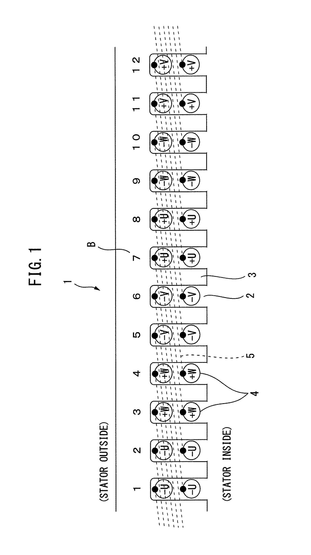
[0029]FIG. 1 illustrates one example of an integral slot type stator 1 of a conventional alternating current electric motor (Conventional Example 1) and illustrates a 6-pole 36-slot winding layout. The integral slot configuration is the case where (number of slots)÷(number of poles) becomes a whole number (in the example which is illustrated in FIG. 1, 36÷6=6). The stator 1 is originally a cylindrical shape, but to facilitate the explanation here, the cylindrical shape stator 1 is illustrated as a developed cross-section which is opened up linearly. Further, in the subsequent conventional examples and examples of the present invention as well, in the explanation of the layout of the windings 4 at the stator 1, this developed cross-sectional view will be used to explain the layout of the stator 1 and windings 4. Note that, FIG. 1 illustrates the cross-section of part of the developed stator 1 (12 slots worth).

[0030]Further, the alternating current is a three-pha...

example 2

CONVENTIONAL EXAMPLE 2

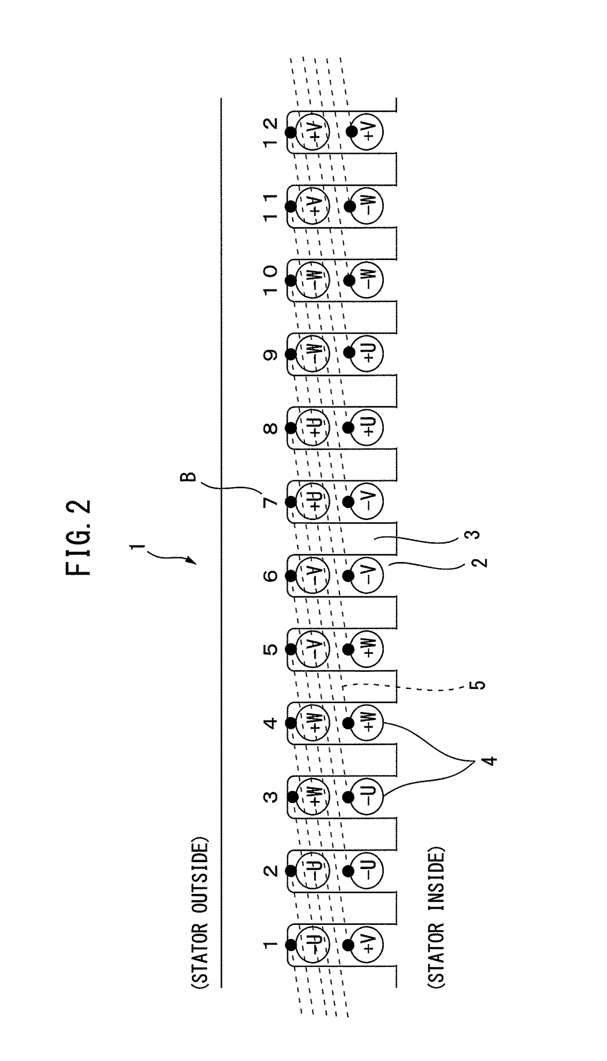
[0032]FIG. 2 illustrates another example of an integral slot type stator 1 of a conventional alternating current electric motor (Conventional Example 2) and illustrates a 6-pole 36-slot winding layout. FIG. 2 also illustrates part of the stator 1 (12 slots worth). The winding layout of Conventional Example 2 differs from the winding layout of Conventional Example 1 in the point that the winding of the second layer of each phase of the two-layer winding is offset by 1 slot to the right side. For this reason, the other winding of the winding 4 at the time of lap winding, as illustrated by the line illustrated by the notation 5, becomes a position separated by (180 degrees×⅚) in terms of electrical angle. In the Conventional Example which is illustrated in FIG. 2, there is a 5 slot coil pitch, so the coil pitch becomes 150 degrees converted to electrical angle.

[0033]Short Pitch Winding of Distributed Winding

[0034]In Conventional Example 2 which is illustrated in F...

example 3

CONVENTIONAL EXAMPLE 3

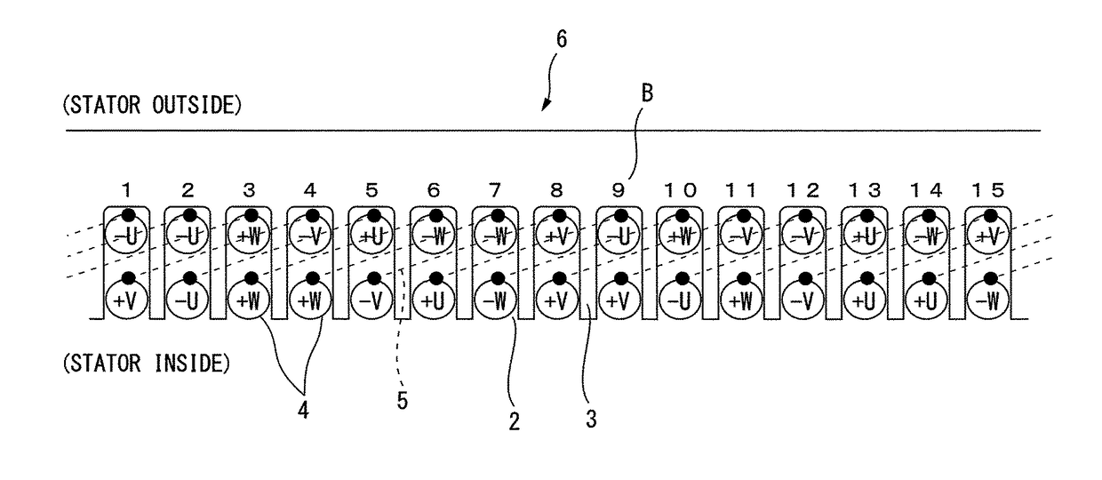
[0035]FIG. 3 illustrates still another example of a fractional slot type stator 6 of a conventional alternating current electric motor (Conventional Example 3) and illustrates a known 4-pole 15-slot winding layout. Two phases are arranged in one slot (two-layer winding). The number of slots occupied by the different phases becomes somewhat uneven. Conventional Example 3 is the case where (number of slots)÷(number of poles)÷(number of phases) becomes 15÷4÷3= 5 / 4 or an irreducible fraction with a denominator of 4 or more. Further, the other winding at the time of lap winding is at a position which is offset by several slots between the first layer and the second layer. Two slots are positioned separated from each other by about 180 degrees in terms of electrical angle.

[0036]In Conventional Example 3, there is a 4 slot coil pitch. The center angle between the slots is 192 degrees converted to electrical angle thereby giving a long pitch winding. Note that, the met...


PUM


Abstract

A three-phase alternating current electric motor wherein when a number of pole pairs of a rotor is P and a number of slots in which stator windings are inserted is N, N / (6P) becomes an irreducible fraction with a value of a denominator of 4 or more and wherein the relation of N>3P stands, in which the motor, for the layout of one layer of windings arranged in the slots, the UVW three-phases are arranged so as to have rotational symmetry of ±120 degrees in terms of mechanical angle from each other and, for the layout of the second layer, the windings are arranged reversed in direction by 180 degrees in electrical angle from the phases of the first layer of windings which have rotational symmetry and offset by M number of slots from the first layer, where T is a particular odd number for the relationship of 4 / 35≦|T−2PM / N|≦ 8 / 35 is given.

Description

BACKGROUND OF THE INVENTION[0001]1. Field of the Invention[0002]The present invention relates to a three-phase alternating current electric motor which is provided with a structure which reduces torque ripple, more particularly relates to a distributed winding three-phase alternating current electric motor where the different phases of windings are wound distributed in several slots.[0003]2. Description of the Related Art[0004]Electric motors which are provided with permanent magnets suffer from pulsation called “cogging torque” and torque fluctuations called “torque ripple”. Cogging torque is a phenomenon where the magnetic attraction force between the armature and rotor in the electric motor finely vibrates depending on the rotation angle and can be confirmed when making the shaft of the electric motor rotate by hand etc. without running a current to the electric motor. The cogging torque changes in magnitude due to the shape of the rotor or stator etc. On the other hand, torque r...

Claims


Application Information

Patent Timeline
Patent Type & Authority Patents(United States)
IPC IPC(8): H02K3/28H02K19/12H02K21/14H02K3/12H02K19/10
CPCH02K3/28H02K3/12H02K19/10H02K19/12H02K21/14H02K2213/03
Inventor ITO, TAKASHI
Owner FANUC LTD
Learn More