Thin layer electrochemical cell with self-formed separator film

A diaphragm layer and battery technology, applied to batteries with solid electrolytes, dry batteries, primary batteries, etc., can solve the problem of not reaching the best contact

Inactive Publication Date: 2009-04-08
鲍尔弗雷克斯有限公司
View PDF7 Cites 0 Cited by
  • Summary
  • Abstract
  • Description
  • Claims
  • Application Information

AI Technical Summary

Problems solved by technology

This, in turn, imposes limitations in that: (i) at least three fabrication steps are required; and (ii) layer-to-layer contact is generally less than optimal

Method used


Image

  • Thin layer electrochemical cell with self-formed separator film
  • Thin layer electrochemical cell with self-formed separator film
  • Thin layer electrochemical cell with self-formed separator film

Examples


Embodiment Construction

[0054] DESCRIPTION OF THE PREFERRED EMBODIMENT

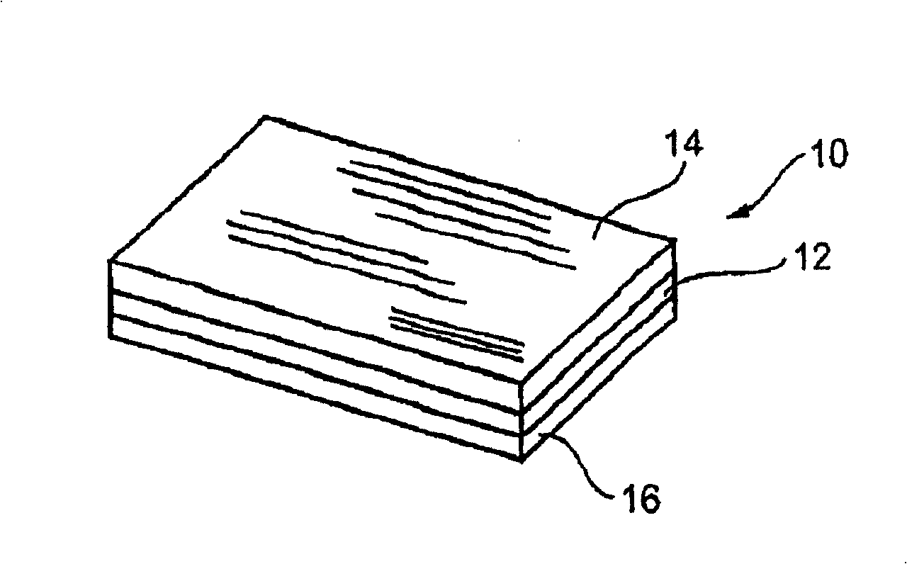
[0055] The present invention relates to thin-layer liquid chemical batteries comprising autogenous separators and methods for their production.

[0056] The principles and operation of the chemical cell of the present invention, as well as the method of the present invention, may be better understood with reference to the drawings and associated descriptions.

[0057] Before explaining at least one embodiment of the invention in detail, it is to be understood that the invention is not limited in application to the details of construction and part arrangement given in the description or illustrations in the following drawings. The invention is capable of other embodiments or of being practiced or carried out in various ways. It is also to be understood that the phraseology and terminology used herein are for the purpose of description and should not be regarded as limiting.

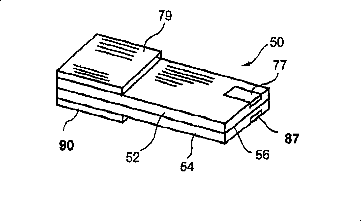
[0058] Watch now figure 2 , wherein a flexible, thi...


PUM


Abstract

A method of forming an electrochemical cell is disclosed. The method comprises contacting a negative pole layer and a positive pole layer one with the other or with an optional layer interposed therebetween. The pole layers and the optional layer therebetween are selected so as to self-form an interfacial separator layer between the pole layers upon such contacting.

Description

technical field [0001] The present invention relates to thin-layer, liquid chemical batteries, preferably of open configuration, for use as battery power sources for the conversion of chemical energy into electrical energy, and in particular to such batteries having a liquid electrolyte and an autogenous porous separator layer between positive and negative electrode layers. Background technique [0002] Batteries fall into two broad categories: liquid batteries, ie, those with a liquid or wet electrolyte, and solid-state batteries, ie, those with the electrolyte in a solid state. The advantage of solid-state batteries over liquid batteries is that they never dry out or leak. However, their main disadvantage compared to liquid batteries is that their operation is largely temperature dependent and many only function properly at high temperatures due to the limited rate of charge diffusion through the solid. Due to the limited diffusion rate, the ratio between the electrical e...

Claims


Application Information

Patent Timeline
Patent Type & Authority Patents(China)
IPC IPC(8): H01M2/16H01M10/04H01M6/06H01M6/12H01M6/18H01M6/22H01M50/403
CPCY02E60/12H01M10/04H01M2300/0002H01M6/181H01M6/188H01M2300/0085H01M2/0292H01M6/22H01M10/0436H01M6/12H01M2/145H01M2/1673Y10T29/49108Y02E60/10H01M50/124H01M50/1245H01M50/403H01M50/46Y02P70/50
Inventor S·卢斯基E·斯乔里
Owner 鲍尔弗雷克斯有限公司
Why Eureka
Try Eureka