Multi-aperture device and method for detecting an object region

a multi-aperture device and object technology, applied in the field of multi-aperture devices and methods for detecting objects, can solve the problems of small depth information between the individual channels of array cameras, counter-active, and inability to accurately detect objects, so as to improve the depth resolution of the object field, the effect of miniaturizing the image detecting device and great lateral distan

Active Publication Date: 2017-09-19
FRAUNHOFER GESELLSCHAFT ZUR FOERDERUNG DER ANGEWANDTEN FORSCHUNG EV
View PDF19 Cites 4 Cited by
  • Summary
  • Abstract
  • Description
  • Claims
  • Application Information

AI Technical Summary

Benefits of technology

[0012]The central idea of the present invention is having recognized that the above object may be achieved by the fact that disparity may be increased by advantageously arranging optical channels on an image converter such that an improved depth resolution of an object region recorded may be achieved.
[0014]It is of advantage with this embodiment that a great lateral distance between optical channels for detecting a sub-region allows an improved depth resolution of the object field. This allows miniaturization of the image detecting devices and / or compensation of the reduction in depth resolution induced by a reduced focal length, for example.

Problems solved by technology

The desired miniaturization of the entire camera setup, however, is counteractive.
Furthermore, in practical realizations, the precision of the depth information is limited by the precision of positioning the two cameras relative to each other (precision of base length).
Since the array camera as a whole is to be small, for example due to integration in mobile devices, like mobile phones, smartphones, notebooks, etc., the distance between the individual channels of the array camera is small and, consequently, the depth resolution is strongly limited.
However, the channels of the array do not transmit the entire object field, but the individual channels each only view sub-regions thereof.
The result of this is that, due to the small base distance of the channels, only a small parallax occurs and thus only small shifts of the sub-images which also result in a limited depth resolution may be observed.

Method used


Image

  • Multi-aperture device and method for detecting an object region
  • Multi-aperture device and method for detecting an object region
  • Multi-aperture device and method for detecting an object region

Examples


Embodiment Construction

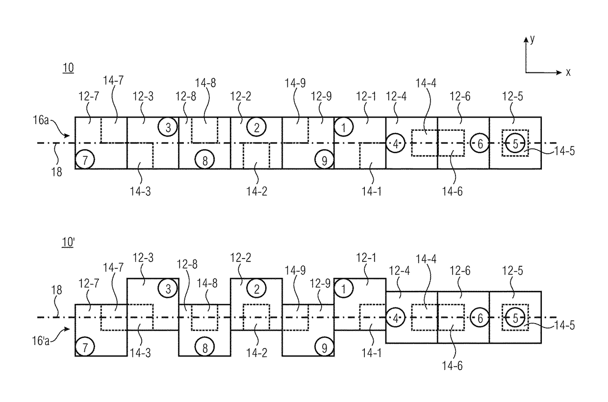
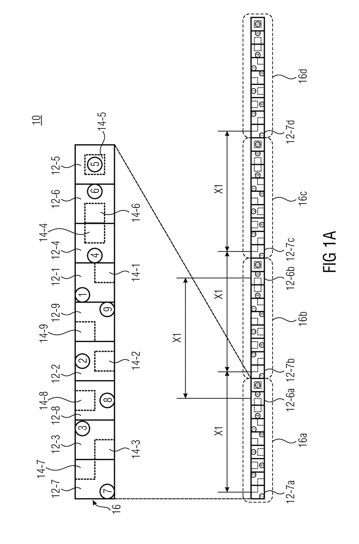
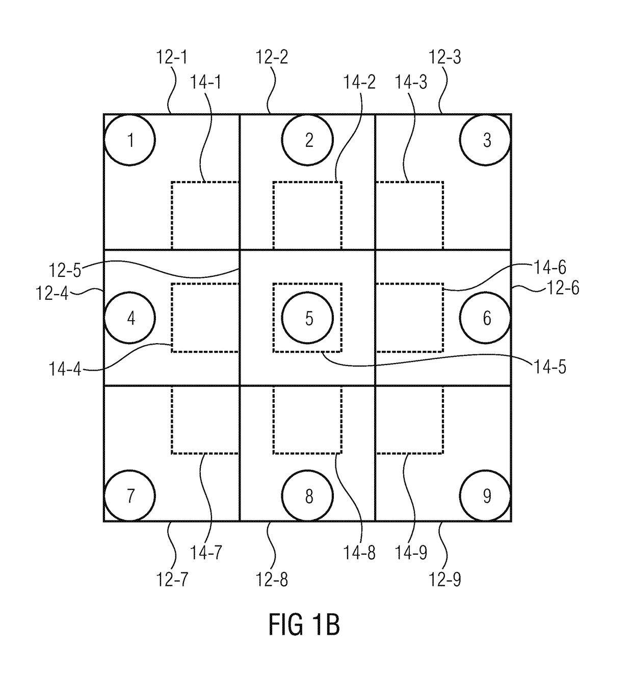
[0040]Before discussing in greater detail below embodiments of the present invention referring to the drawings, it is pointed out that identical elements, objects and / or structures or those of equal function or equal effect are, in the different figures, provided with same reference numerals such that the description of these elements illustrated in different embodiments is mutually exchangeable or mutually applicable.

[0041]In the following discussion, a multi-aperture device is to be understood to be a device for optically detecting an object region, like an image. The multi-aperture device may, for example, be a camera configured to detect an image with several pixels. The multi-aperture approach allows a compact setup of the device. A pixel may, for example be detected by a charge-coupled device (CCD) or a complementary metal oxide semiconductor (CMOS) image sensor. The image sensor may comprise one or several image sensor regions which may be arranged in one or several image con...


PUM


Abstract

The invention describes a multi-aperture device for detecting an object region having at least two optical channels for detecting a first sub-region of the object region and at least two optical channels for detecting a second sub-region of the object region. The optical channels for detecting the first and second sub-regions are arranged in an interlaced manner in a one-row structure, wherein the first and second sub-regions overlap at least partly.

Description

CROSS-REFERENCE TO RELATED APPLICATIONS[0001]This application is a continuation of copending International Application No. PCT / EP2014 / 073457, filed Oct. 31, 2014, which is incorporated herein by reference in its entirety, and additionally claims priority from German Application No. 102013222780.9, filed Nov. 8, 2013, which is also incorporated herein by reference in its entirety.BACKGROUND OF THE INVENTION[0002]The invention relates to a multi-aperture device and to a method for detecting an object region.[0003]Conventional cameras are based on the single-aperture principle. A continuous image of the object is taken here, wherein neighboring regions in the object are also neighboring in the image. In order to record depth information, in most cases two cameras exhibiting a lateral distance to each other are used (stereoscopy). The cameras view the object from different angles (parallax), in correspondence with the distance of the cameras (base length) and the object distance. Conseq...

Claims


Application Information

Patent Timeline
Patent Type & Authority Patents(United States)
IPC IPC(8): H04N13/02H04N5/225H04N13/232
CPCH04N13/0217H04N5/2258H04N13/025H04N13/0228H04N13/0232H04N13/232H04N13/218H04N13/229H04N13/25H04N23/45
Inventor WIPPERMANN, FRANKBRUECKNER, ANDREASBRAEUER, ANDREAS
Owner FRAUNHOFER GESELLSCHAFT ZUR FOERDERUNG DER ANGEWANDTEN FORSCHUNG EV
Why Eureka
Try Eureka