Method and apparatus for load and additional property measurement

a technology of additional property and measurement method, which is applied in the direction of apparatus for force/torque/work measurement, manufacturing tools, instruments, etc., can solve the problems of additional property loss and other problems, and achieve the effect of improving the depth resolution of acquired data, preventing joint corrosion, and improving the accuracy of grid methods

Active Publication Date: 2015-12-08
JENTEK SENSORS
View PDF5 Cites 4 Cited by
  • Summary
  • Abstract
  • Description
  • Claims
  • Application Information

AI Technical Summary

Benefits of technology

[0008]One or more additional properties may also be measured. In some embodiments, the additional property relates to the structural material beyond the foil. The structural material may be “structural”, for example, to an aircraft or other critical piece of machinery or a facility such as a pipe or vessel mount. The additional property may be related to a damage mode associated with the structural material or to degradation of an otherwise functional material such as a coating or temperature sensitive material. In some embodiments the additional property is material loss as may be caused by corrosion of the structural material. In another embodiment the additional property may be a crack in the structural material. In yet other embodiments, the additional property may be any of a gap distance, a layer thickness, a temperature, a stress, a degraded metallurgical or other material property, or an electrical property of the material. Any suitable additional property may be measured. In some embodiments the additional property of interest relates to a material or material layer further away from the sensor than the foil layer. In some embodiments the sensor is configured to allow multiple depths of penetration beyond the conducting foil layer to discern properties near the sensor and farther away, or in multiple layers of a structure or on an adjacent surface and the far side of a neighboring layer. In some embodiments the sensor may be mounted within a gasket to form a sensor gasket. The materials and configuration of the sensor gasket may provide a barrier to moisture ingress into the joint to prevent corrosion of the joint.
[0009]In an embodiment where an eddy current sensor, such as an MWM, is used, one or more “higher” frequency sensor excitation may be used to determine the properties of the foil and distance to the foil. As stated above the distance to the foil may be related to a load applied to the clamped structure in which the sensor has been embedded. One or more relatively “lower” frequency excitations may be used to determine the additional property of interest. In some embodiments, a segmented field sensor with two or more drive to sense gaps integrated into the sensor is used to improve the depth resolution of the acquired data and allow estimation of additional properties of the neighboring material or additional operational variables such as temperatures or loads that can be discerned from the sensor responses for multiple frequencies or multiple segments of the applied field as measured at multiple sensing elements properly placed relative to a drive conductor or for an alternative sensor construct.
[0010]In some embodiments, grid methods may be used to relate the sensor response (e.g., voltage, current, impedance) to the load and / or additional property of interest. In some embodiments the accuracy of the grid methods may be enhanced by assuming certain properties of the material stack up are known. For example, one or more properties of the foil may be accurately known such that the grid methods need to be used to provide an estimate of such properties from measurement.

Problems solved by technology

In some embodiments the additional property is material loss as may be caused by corrosion of the structural material.

Method used


Image

  • Method and apparatus for load and additional property measurement
  • Method and apparatus for load and additional property measurement
  • Method and apparatus for load and additional property measurement

Examples


Embodiment Construction

[0036]A description of example embodiments of the invention follows.

[0037]The inventors have recognized and appreciated the need for embedded load monitoring and structural health monitoring capability on critical structures. A sensor and sensing method is disclosed that provides simultaneous load and structural health monitoring.

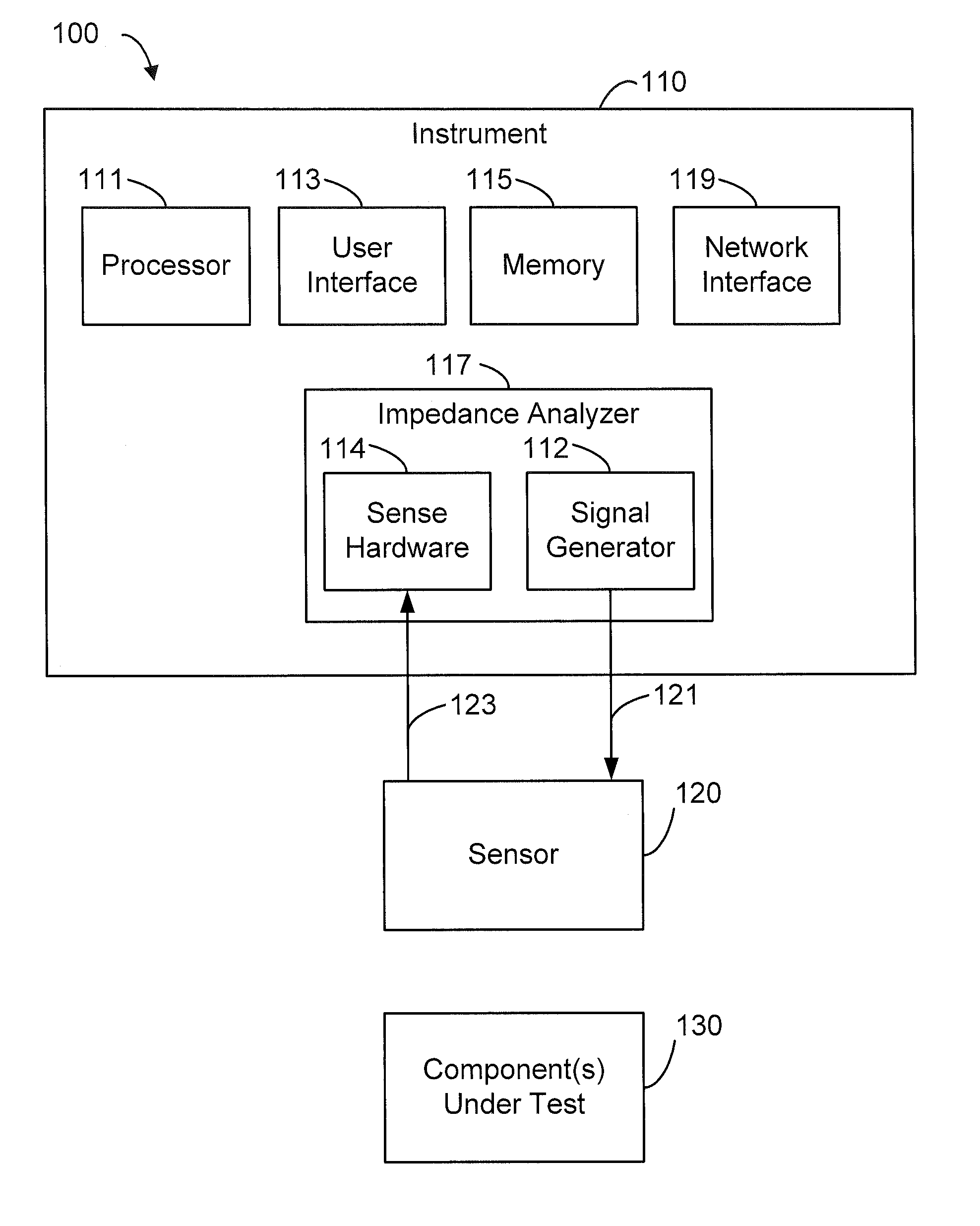
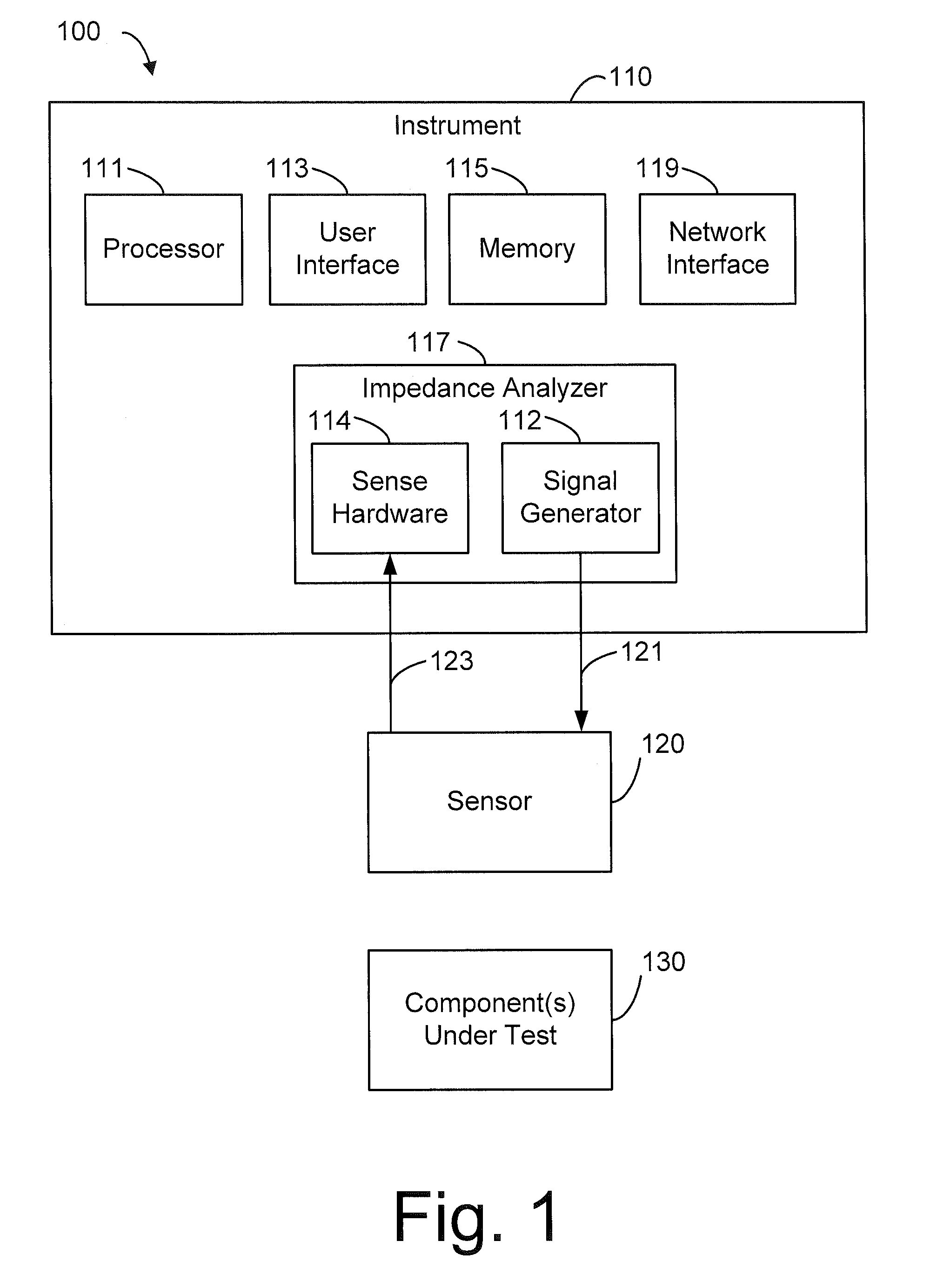
[0038]Prior to discussing embodiments of the sensor itself, a system with which the sensor may be operated is presented. FIG. 1 shows a block diagram of a measurement system 100 for monitoring test object 130 with a sensor 120. Measurement system 100 includes an instrument 110 for exciting and measuring sensor 120. Instrument 110 is configured to provide excitation signals 121 to sensor 120 and measure the resulting response signals 123 of sensor 120. Measured response signals 123 may be processed to estimate properties of interest, such as electrical properties (e.g., conductivity, permeability, and permittivity), geometric properties (e.g., thickness, sen...


PUM

PropertyMeasurementUnit
thickaaaaaaaaaa
thickaaaaaaaaaa
thicknessaaaaaaaaaa

Abstract

A system and method for measuring load and an additional property using a sensor gasket embedded between two components. The sensor gasket may include a sensor layer and a conductive layer. A gap between the sensor layer and conductive layer may be filled with a load sensitive material. The thickness of the load sensitive material varies with the load applied to the two components between which the sensor gasket sits. The sensor operates in a first mode to obtain a sensor measurement that depends on the distance between the sensor layer and conductive layer. The sensor measurement then used to estimate the applied load. The sensor operates in a second mode to estimate a property of one or both of the components. The property of interest may be cracking, material loss due to corrosion, temperature, or another property of the component.

Description

[0001]This application claims the benefit of U.S. Provisional Application No. 61 / 617,168, filed on Mar. 29, 2012.[0002]The entire teachings of the above application are incorporated herein by reference.BACKGROUND OF THE INVENTION[0003]Critical fastener locations on aircraft platforms require regular inspection to verify that cracking, corrosion or other deleterious conditions are not present. Also, critical locations on other structures, such as bridges, piping systems, pipelines, railroad rails, at mounting locations for vessels, drive trains, pumps and other structures and facilities require either inspections for damage or operational variable monitoring. Operational variables of interest include temperature and stresses / loads at critical interfaces and at varied depths into materials near joints, mounts and at other critical locations.[0004]Inspection can require disassembly to gain access to critical locations. This disassembly often requires extensive man-hours incurring costs...

Claims


Application Information

Patent Timeline
Patent Type & Authority Patents(United States)
IPC IPC(8): B25B23/14G01L5/24G01L1/12G01L1/26
CPCG01L1/12G01L1/26
Inventor SCHLICKER, DARRELL E.GOLDFINE, NEIL J.
Owner JENTEK SENSORS
Why Eureka
Try Eureka