Stent-graft with fixation elements that are radially confined for delivery

a technology of fixation elements and stents, applied in the field of tubular prostheses, can solve the problems of damage to the inner wall, penetration, tear or otherwise damage to the external delivery sheath, and the difficulty of reducing the crossing profil

Active Publication Date: 2017-09-26
ENDOSPAN
View PDF602 Cites 0 Cited by
  • Summary
  • Abstract
  • Description
  • Claims
  • Application Information

AI Technical Summary

Benefits of technology

This design reduces the risk of sheath damage, allows for a smaller crossing profile, and improves anchoring within blood vessels by strategically deploying fixation members to penetrate and secure the stent-graft, enhancing the deployment process and reducing trauma to the sheath.

Problems solved by technology

When the stent-graft is in the delivery state, the radially-constrained fixation members are unlikely to penetrate, tear, or otherwise damage the external delivery sheath of the delivery catheter.
The traumatic nature of fixation barbs presents a technical challenge in reducing the crossing profile and maintaining the integrity of external sheaths of delivery systems of stent-grafts.
Fixation barbs, because they are traumatic, are often prone to damage the inner wall of the polymeric external delivery sheath that externally confines the stent-graft when the stent-graft is in its radially compressed state.
Because most fixation barbs are directed in the distal to proximal direction, pushing an external sheath over the stent in a direction opposite to the direction in which the barbs point is usually traumatic to the inner wall of such an external delivery sheath.

Method used


Image

  • Stent-graft with fixation elements that are radially confined for delivery
  • Stent-graft with fixation elements that are radially confined for delivery
  • Stent-graft with fixation elements that are radially confined for delivery

Examples


Embodiment Construction

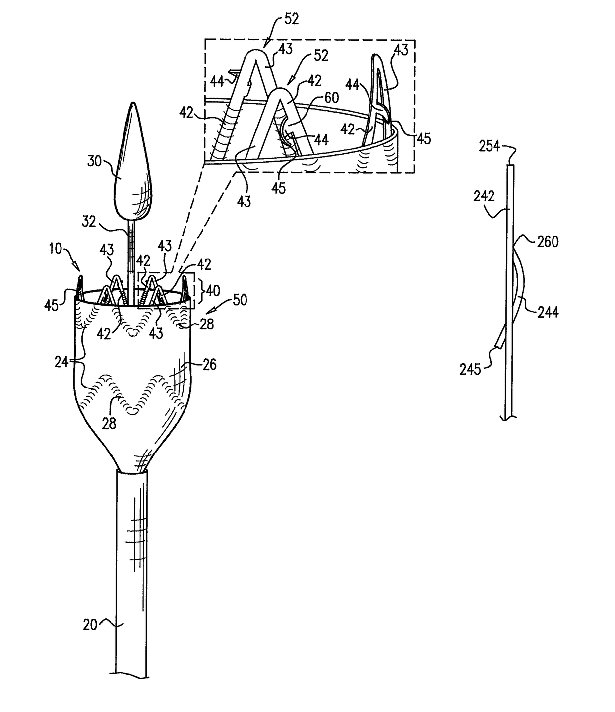
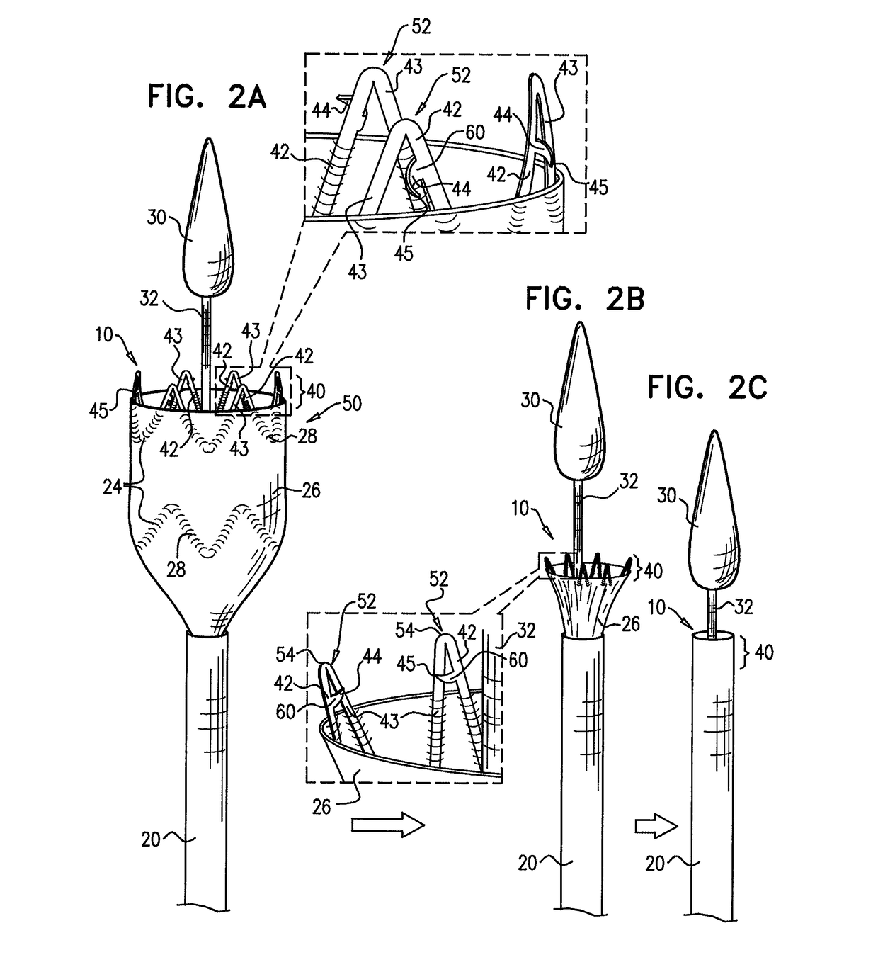
[0104]Reference is made to FIGS. 2A-C and 3A-C. FIGS. 2A-C are schematic illustrations of an endovascular stent-graft 10 during several stages of loading the stent-graft into an external delivery sheath 20 of a delivery catheter of a delivery system, in accordance with an application of the present invention. FIGS. 3A-C are schematic illustrations of stent-graft 10 during several stages of deployment of the stent-graft from external delivery sheath 20, in accordance with an application of the present invention.

[0105]Stent-graft 10 comprises a flexible stent member 24 and a tubular fluid flow guide 26. Stent-graft 10 is configured to assume (a) a radially-compressed delivery state, typically when the body is positioned in sheath 20, such as shown in FIGS. 2C and 3A, and (b) a radially-expanded deployment state, when not positioned in the sheath. FIGS. 2A and 3C show a distal portion of the body in the radially-expanded state. FIGS. 2B and 3B show a distal portion of the body partiall...


PUM


Abstract

An endovascular stent-graft is provided that includes a flexible stent member, which includes a plurality of struts, which are shaped so as to define a generally circumferential section; a tubular fluid flow guide, which includes a graft material, and which is attached to the stent member; and at least one fixation member shaped so as to define a base at a first end thereof and a sharp tip at a second end thereof. The base is coupled to one of the struts that are shaped so as to define the generally circumferential section. When the stent-graft is in a radially-expanded deployment state, the fixation member protrudes radially outward. When the stent-graft is in a radially-compressed delivery state, at least a portion of the fixation member between the base and the sharp tip is convex as viewed from outside the stent-graft, such that the sharp tip points radially inward.

Description

CROSS REFERENCE TO RELATED APPLICATIONS[0001]This application is a National Stage of International Application No. PCT / IL2012 / 000190 filed May 15, 2012, the contents of all of which are incorporated herein by reference in their entirety.FIELD OF THE APPLICATION[0002]This present application relates generally to prostheses and surgical methods, and specifically to tubular prostheses, including endovascular stent-grafts, and surgical techniques for using the prostheses to maintain patency of body passages such as blood vessels, and treating aneurysms.BACKGROUND OF THE APPLICATION[0003]Endovascular prostheses are sometimes used to treat aortic aneurysms. Such treatment includes implanting a stent or stent-graft within the diseased vessel to bypass the anomaly. An aneurysm is a sac formed by the dilation of the wall of the artery. Aneurysms may be congenital, but are usually caused by disease or, occasionally, by trauma. Aortic aneurysms, which commonly form between the renal arteries a...

Claims


Application Information

Patent Timeline
Patent Type & AuthorityPatents(United States)
IPC IPC(8): A61F2/06A61F2/82A61F2/95A61F2/07A61F2/848A61F2/966
CPCA61F2/95A61F2/07A61F2/82A61F2/966A61F2002/075A61F2002/8483
InventorSHALEV, ALON
OwnerENDOSPAN