Impingement cooling mechanism, turbine blade and combustor
a cooling mechanism and turbine blade technology, applied in mechanical equipment, machines/engines, light and heating equipment, etc., can solve problems such as affecting the cooling effect of the blade main body, and achieve the effects of increasing the cooling effect of the impingement, increasing the heat transfer coefficient, and effectively utilizing the cooling gas
- Summary
- Abstract
- Description
- Claims
- Application Information
AI Technical Summary
Benefits of technology
Problems solved by technology
Method used
Image
Examples
first embodiment
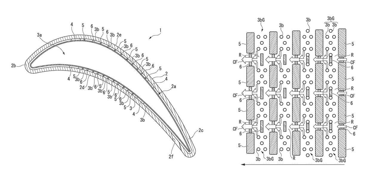
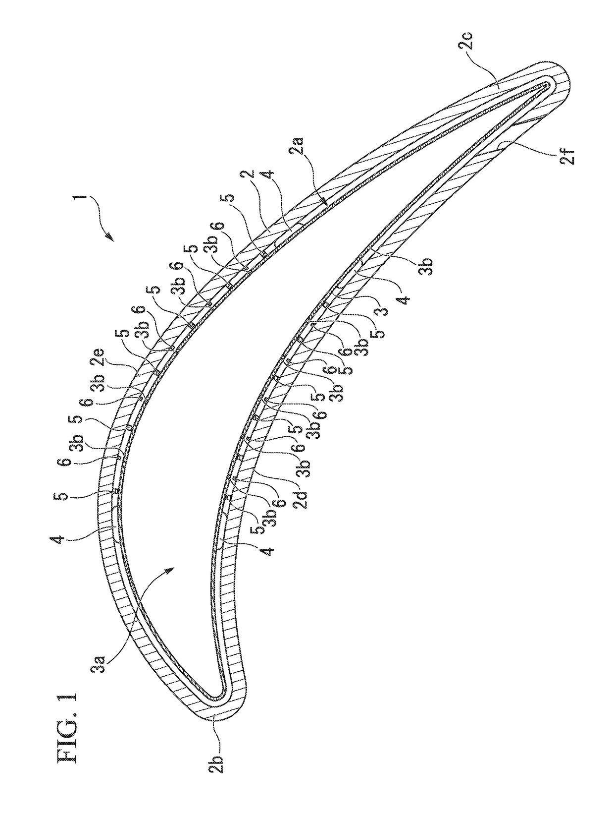
[0033]FIG. 1 is a cross-sectional view that shows the outline configuration of a turbine blade having the impingement cooling mechanism of the present embodiment. A turbine blade 1 is provided with a blade main body 2 and an impingement plate 3.
[0034]The blade main body 2 forms the outer shape of the turbine blade 1, and has therein a space (interior space) 2a, and the blade main body 2, which serves as the cooling target in the impingement mechanism, is provided with a leading edge portion (blade leading edge portion) 2b, a trailing edge portion (blade trailing edge portion) 2c, a front-side blade surface (blade front) 2d, and a back-side blade surface 2e. Also, a through-hole 2f that penetrates from the interior space 2a to the outer portion of the blade main body 2 is formed at the trailing edge portion 2c.
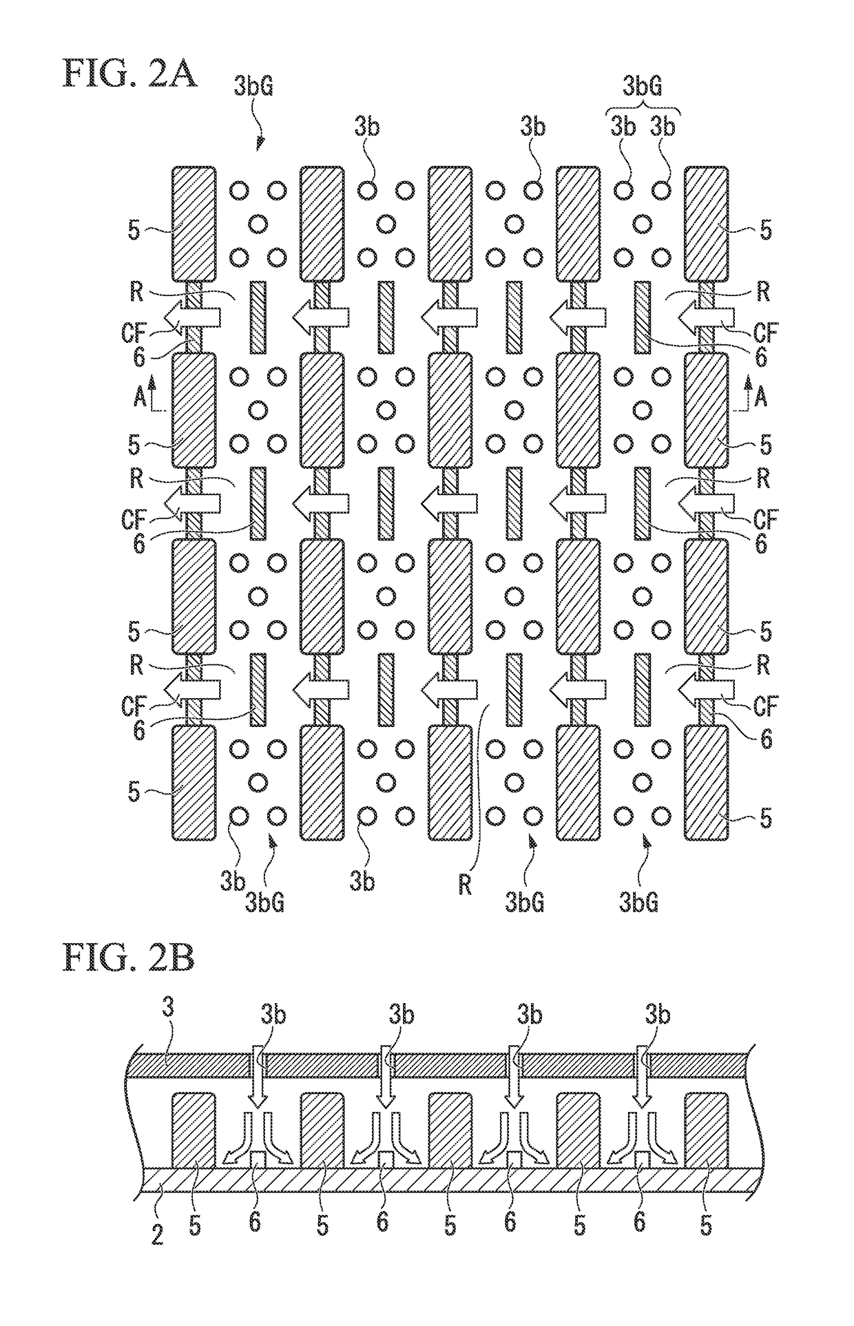
[0035]The impingement plate 3 has an analogous outer shape approximately equivalent to the outer shape of the interior space 2a of the blade main body 2, and functions as a fa...
second embodiment
[0051]FIG. 3A and FIG. 3B are drawings for describing the turbine blade that has the impingement cooling mechanism of the present embodiment. FIG. 3A is a plan view that schematically shows the main portions of the inner surface side of the blade main body 2 (that is to say, a plan view that shows the outline configuration of the impingement cooling mechanism). Also, FIG. 3B is a cross-sectional view along A-A line of FIG. 3A.
[0052]The point of difference between the turbine blade (impingement cooling mechanism) of the present embodiment and the turbine blade (impingement cooling mechanism) shown in FIG. 2A and FIG. 2B is the point of the sizes of the blocking plate 5 and the turbulent flow promoting portion 6 not being uniform, and differing along the flow direction of the crossflow CF.
[0053]In contrast, the width of the blocking plate 5 that is arranged on the upstream side of the impingement hole group 3bG is relatively wider on the upstream side of the crossflow CF, and relative...
third embodiment
[0057]FIG. 4A and FIG. 4B are drawings for describing a turbine blade that has the impingement cooling mechanism of the present embodiment. FIG. 4 is a plan view that schematically shows the main portions of the inner surface side of the blade main body 2 (that is to say, a plan view that shows the outline configuration of the impingement cooling mechanism). Also, FIG. 4B is a cross-sectional view along A-A line of FIG. 4A.
[0058]The point of difference between the turbine blade (impingement cooling mechanism) of the present embodiment and the turbine blade (impingement cooling mechanism) shown in FIG. 2A and FIG. 2B is the point of the impingement holes 3b being arranged in the flow path R of the crossflow CF that is regulated by the blocking plates 5. That is to say, in the present embodiment, an in-flow-path impingement hole group G1 that consists of four of the impingement holes 3b is formed in the flowpath between the impingement hole groups 3bG; 3bG. The blocking plates 5 are n...
PUM
 Abstract
Description
Claims
Application Information
 - R&D
- Intellectual Property
- Life Sciences
- Materials
- Tech Scout
- Unparalleled Data Quality
- Higher Quality Content
- 60% Fewer Hallucinations
Browse by: Latest US Patents, China's latest patents, Technical Efficacy Thesaurus, Application Domain, Technology Topic, Popular Technical Reports.
© 2025 PatSnap. All rights reserved.Legal|Privacy policy|Modern Slavery Act Transparency Statement|Sitemap|About US| Contact US: help@patsnap.com


