Bayonet type locking ring of a circular electrical connector

a technology of locking ring and circular electrical connector, which is applied in the direction of coupling device connection, electrical apparatus, coupling/disassembly parts, etc., can solve the problems of complex and costly resources, complex and expensive operations, and inability or difficulty to mold an optimized piece, etc., to achieve constant thickness, low cost, and the effect of optimizing the design of the pi

Active Publication Date: 2017-10-03
SOURIAU
View PDF16 Cites 3 Cited by
  • Summary
  • Abstract
  • Description
  • Claims
  • Application Information

AI Technical Summary

Benefits of technology

[0015]The locking ring is made of two pieces, and the parting surface is located between the two locking ramp parts. The functional shapes of these two parts can thus be made easily regardless of the embodiment selected, with no need for tools or complex methods. Assembly is very simple and fast, and therefore economical.
[0027]Regarding the second piece, it is reduced to the strict minimum. The choice of material is related to the use of the connector. Thus, to improve the lifespan of the connector, the second piece is in metal, which makes it more friction resistant. To reduce its weight, the second piece is in very high performance thermoplastic. Thus, the surface is protected, and in that case, the second piece avoids corrosion risks.

Problems solved by technology

In both cases, the resources required are complex and costly, because the ramps of the locking system need to be made inside the piece, and are thus in a back-draft position.
The complexity of the mold makes it impossible or difficult to mold an optimized piece due to constraints relating to injection, the low mass in some locations and constant thicknesses.
These operations are complex and expensive and can generate scrap.

Method used


Image

  • Bayonet type locking ring of a circular electrical connector
  • Bayonet type locking ring of a circular electrical connector
  • Bayonet type locking ring of a circular electrical connector

Examples


Embodiment Construction

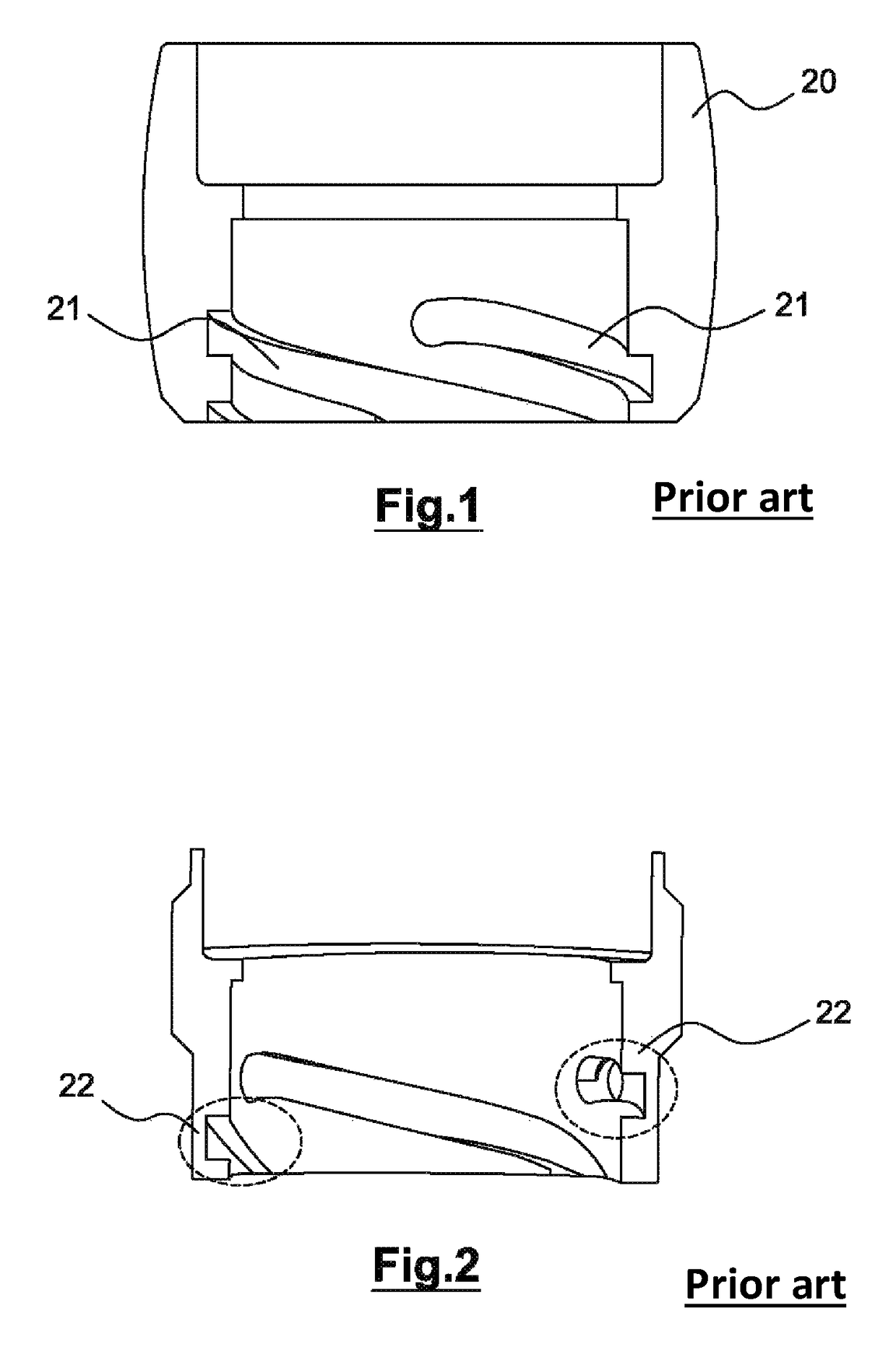
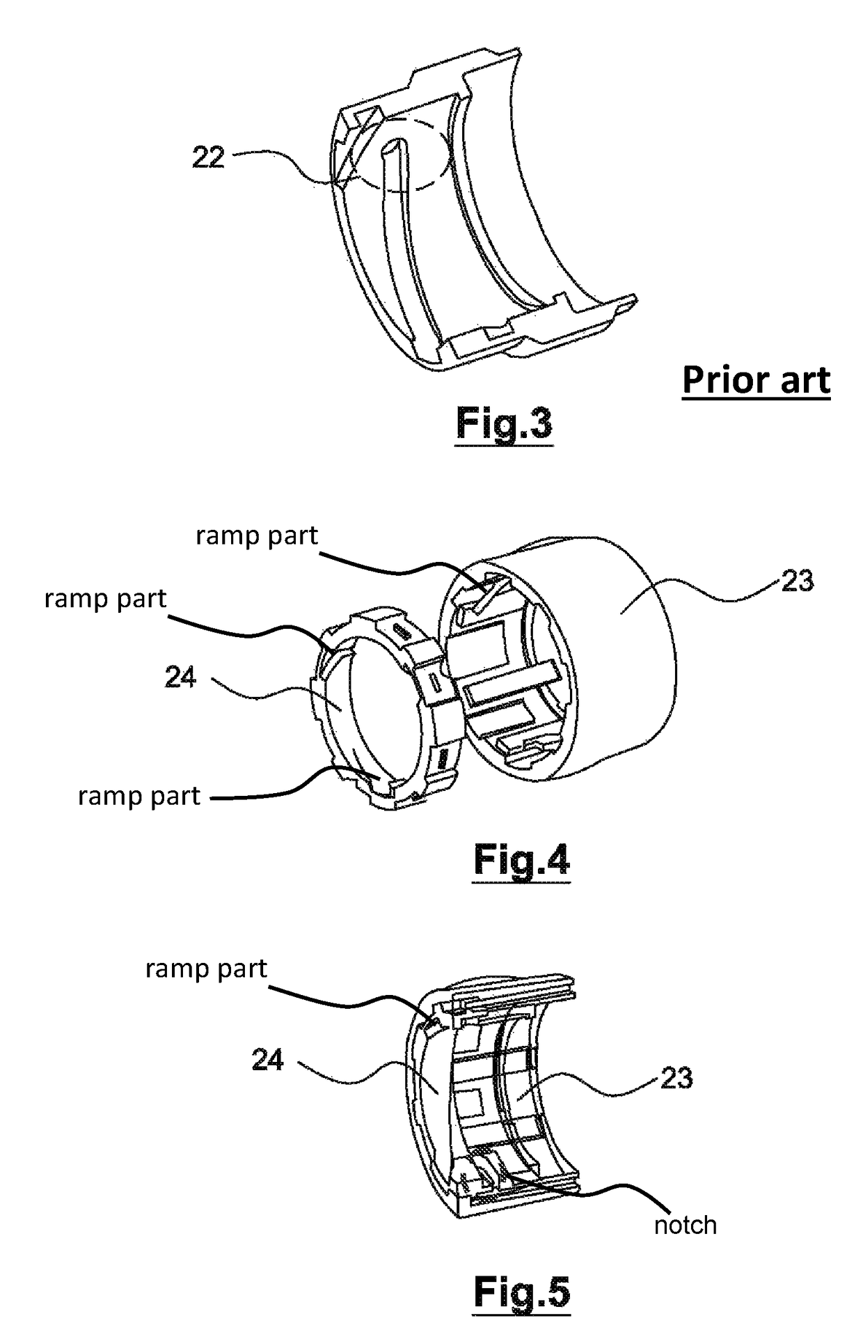
[0042]FIGS. 1 to 3 have been described above.

[0043]FIG. 4 shows the first piece 23 and the second piece 24 before they are assembled. The first piece 23 comprises notches distributed over the entire circumference of the internal surface. The second piece 24 comprises notches distributed over the entire circumference of the external surface. The notches of the first piece 23 and the notches of the second piece 24 are complementary.

[0044]FIG. 5 shows the assembly of the first piece 23 and the second piece 24. When these two pieces are assembled by displacement in the longitudinal direction of the first piece 23, the second piece 24 can no longer rotate in relation to the first piece 23. The notches make it possible to prevent such rotation.

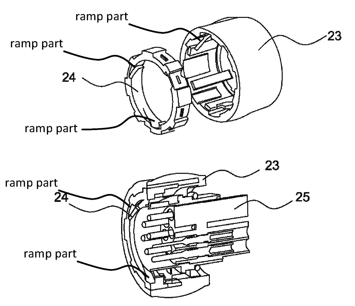
[0045]FIGS. 6 and 7 show the positioning of an electrical connector 25 in the locking ring. The first piece 23 and the second piece 24 are assembled before the electrical connector is positioned.

[0046]FIGS. 8 and 11-13 represent a sectional view of ...


PUM


Abstract

A bayonet type locking ring of a circular electrical connector. A first piece with the shape of a cylindrical ring extends from one end to the other. The first piece is made of thermoplastic material, and includes notches distributed over the internal face of the first piece adjacent to one end and a first ramp part on the internal face of the first piece. A second piece with the shape of a cylindrical ring, and includes notches distributed over its external face and a second ramp part on the internal cylindrical surface. The first piece and the second piece are assemblable such that the notches of the second piece fit in the notches of the first piece, and prevent the second piece from rotating in relation to the first piece. The second ramp part of the second piece complements the first ramp part of the first piece.

Description

RELATED APPLICATIONS[0001]This application claims priority from French Patent Application No. 15 54925 filed Jun. 1, 2015, which is incorporated herein by reference in its entirety.TECHNICAL FIELD OF THE INVENTION[0002]This invention relates to a locking ring. In particular, it applies to a bayonet type locking ring of a circular electrical connector, which happens to be the most complex to produce.BACKGROUND OF THE INVENTION[0003]All bayonet locking rings are of the single-piece type, meaning that they are either molded or machined in a single piece.[0004]In both cases, the resources required are complex and costly, because the ramps of the locking system need to be made inside the piece, and are thus in a back-draft position.[0005]FIG. 1 illustrates the case of a molding 20 with ramps 21. The mold must have a collapsible core in order to unmold the ramps.[0006]The complexity of the mold makes it impossible or difficult to mold an optimized piece due to constraints relating to inje...

Claims


Application Information

Patent Timeline
Patent Type & Authority Patents(United States)
IPC IPC(8): H01R13/62H01R13/625H01R13/508H01R13/506
CPCH01R13/625H01R13/508H01R13/506
Inventor TROQUET, GILLESFEURPRIER, JULIEN
Owner SOURIAU
Why Eureka
Try Eureka