Brake system of a drum brake

a drum brake and brake system technology, applied in the direction of mechanically actuated drum brakes, actuators, braking members, etc., can solve the problems of brake cylinders for wedge drum brakes considerably more expensive compared, load on the connection site of the brake cylinder on the carrier unit, etc., to reduce the occurrence of notching effect, reduce the bending load in the connecting element, and increase the service life and maximum possible bending moments

Active Publication Date: 2016-10-11
SAF HOLLAND GMBH
View PDF13 Cites 0 Cited by
  • Summary
  • Abstract
  • Description
  • Claims
  • Application Information

AI Technical Summary

Benefits of technology

[0006]In a preferred embodiment, the distance d1 of the center of gravity of the brake cylinder to the first connection section is in a relationship of 0.05 to 0.9, preferably 0.1 to 0.8, and particularly preferably 0.3 to 0.7 to the distance d2 of the center of gravity of the brake cylinder from the second connection section. Preferably, the distance of the first connection section to the second connection section is the length or the extension of the connecting element along the transmission axis. Here, the weight or the inertia force of the brake cylinder acts departing from its center of gravity with a lever arm, which results from the sum of the distance of the center of gravity of the brake cylinder to the first connection section and the length of the connecting element. In order to keep the total lever arm as small as is possible, it is preferred that the center of gravity of the brake cylinder is arranged as close as is possible to the first connection section, wherein in particular the moments acting in the first connection section or between the first connection section and the brake cylinder may be kept low due to the short lever arm. The further away the center of gravity of the brake cylinder is arranged from the first connection section, the larger the moments or bending moments acting in the first connection section between the brake cylinder and the connecting element. The lower limit for this relationship of preferably 0.05 is characterized by a particularly short brake cylinder or a brake cylinder, which extends particularly little along the transmission axis in relation to a very long transmission element. However, it may also be preferred to use a large cylinder with a long length of stroke, wherein in this case the relationship of d1 to d2 is large. The preferred range of the relationship of the distance d1 to the distance d2 makes it possible to reach the right compromise between the optimum bending moment relationship at the connection sections and the optimum mounting position of the brake cylinder in the area of the wheel suspension. Preferably, a multiple of the bending moment acting on the first connection section acts on the second connection section. The mounting position of the brake cylinder preferably ensures a good accessibility for assembly work on the brake cylinder, ensures the required distance of the hydraulic lines connected to the brake cylinder from rotating components, and ensures that in the case of vibrations of the brake system there is little probability of resonances.
[0014]In a further preferred embodiment, the first connection section has an undercut, which may be made to form-fittingly or positively engage a corresponding geometry of the brake cylinder. Preferably, there may be provided a bayonet lock, for example, where the brake cylinder is guided along the transmission axis against the connection section and by slightly turning it about the transmission axis or by rotating it about the transmission axis it comes into positive engagement with a respective undercut on the first connection section. It may be further preferred to fix the brake cylinder by means of additional fastening elements or an additional fastening element after said rotation position has been set. This embodiment is advantageous in particular in that it provides for a fast and simple assembly with only a few assembly steps.

Problems solved by technology

Up to now, only brake cylinders especially designed for wedge drum brakes could be fixed to the carrier unit via a longish tube-shaped element, wherein in particular due to the high weight and the long lever arm, tremendous moments cause loads on and fatigue of the connection site of the brake cylinder on the carrier unit.
Furthermore, the brake cylinders for wedge drum brakes are considerably more expensive compared to brake cylinders for disc brake systems since they are not manufactured in mass production processes.

Method used


Image

  • Brake system of a drum brake
  • Brake system of a drum brake

Examples


Embodiment Construction

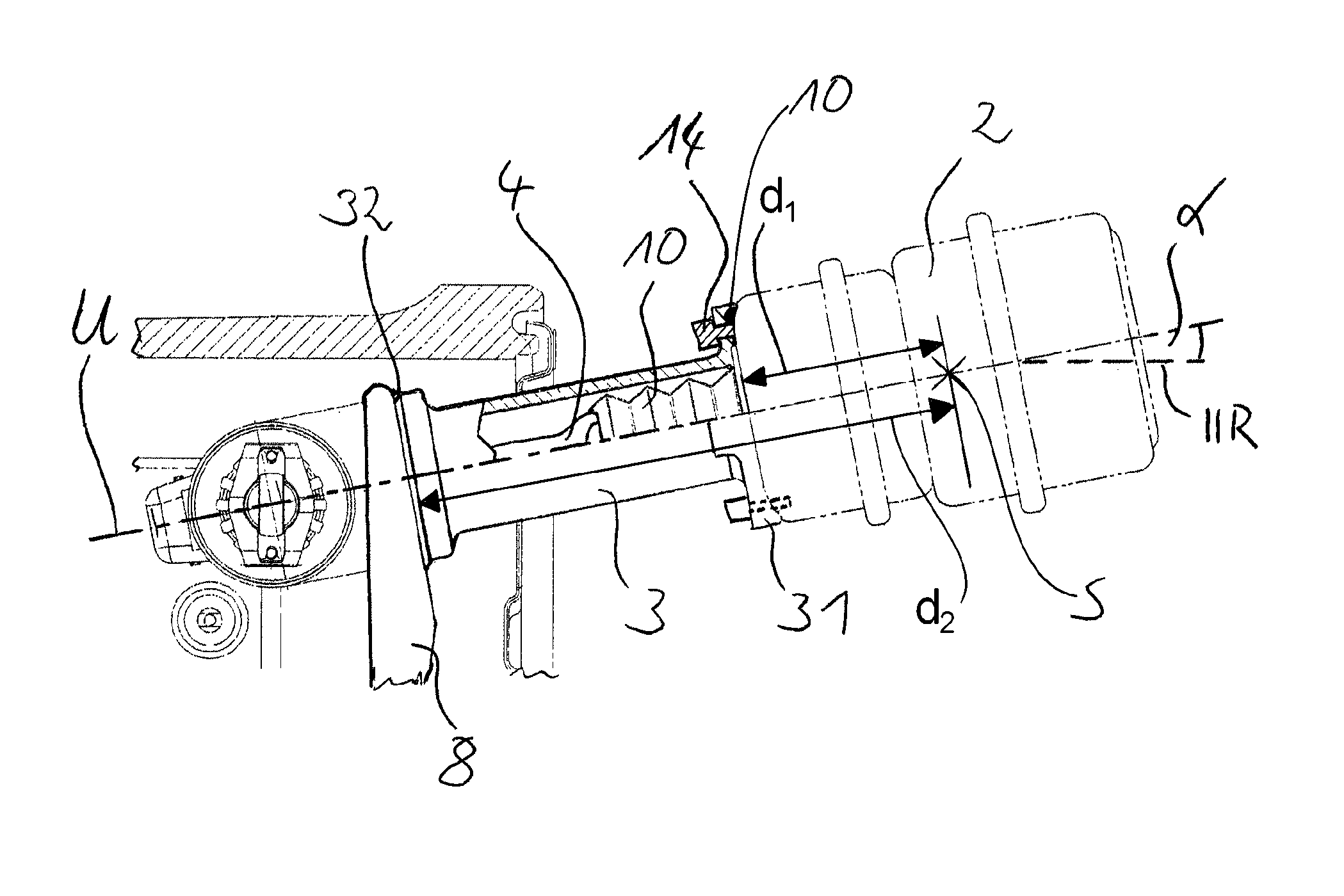
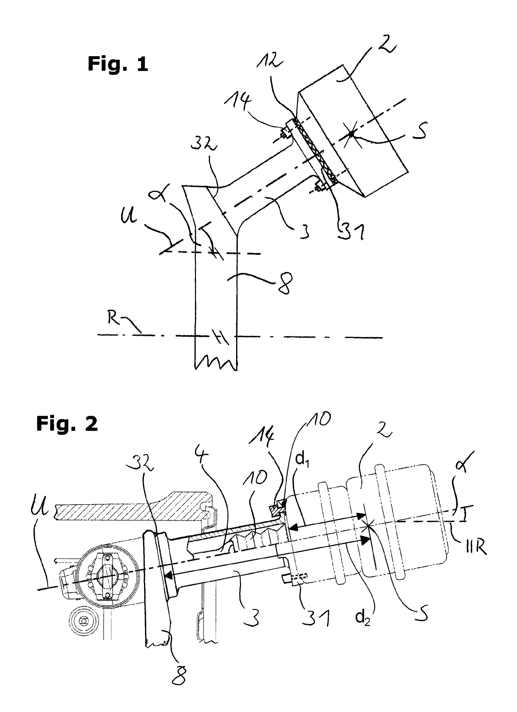
[0018]FIG. 1 shows a preferred embodiment of the brake system according to the invention, comprising a carrier unit 8, a brake cylinder 2, and a connecting element 3. The connecting element 3 is preferably designed as an integral part of the carrier unit 8, wherein it is fixed to the carrier unit 8 in a second connection section 32. Furthermore, the connecting element 3 comprises a connection section 31, which particularly preferably is construed as a flange and serves for accommodating or fixing the brake cylinder 2. The carrier unit 8 preferably corresponds to the brake carrier of a known brake system and extends essentially transverse to a wheel axis R. The connecting element 3 extends essentially along a transmission axis U, which is inclined at an angle α relative to the wheel axis. The first connection section 31 of the connecting element 3 is preferably formed as a flange, wherein fastening means 14 may engage the first connection section 31 in order to fix the brake cylinder...


PUM


Abstract

A brake system of a drum brake includes a carrier unit and a brake cylinder, wherein a connecting element is provided, which has a first connection section for fixing the brake cylinder and is fixed in a second connection section to the carrier unit wherein, the first connection section is arranged offset to the second connection section while being parallel relative to the wheel axis, and wherein the first connection section can be fixed directly to the brake cylinder in order to keep the distance between the center of gravity of the brake cylinder and the first connection section low.

Description

BACKGROUND OF THE INVENTION[0001]The present invention relates to a brake system of a drum brake, comprising a carrier unit and a brake cylinder, in particular for use in commercial vehicles or utility vehicles.[0002]Brake systems of wedge drum brakes are known in the prior art, wherein the wheel of a utility vehicle is slowed down by means of a brake drum rotating with the wheel and brake shoe elements engaging the brake drum. In order to fix the non-rotating components of the brake system to the frame of the utility vehicle, a carrier unit or a brake carrier is used in a known manner, which secures or supports for example components such as brake shoe elements or brake cylinders against displacement relative to the vehicle frame of the utility vehicle. Up to now, only brake cylinders especially designed for wedge drum brakes could be fixed to the carrier unit via a longish tube-shaped element, wherein in particular due to the high weight and the long lever arm, tremendous moments ...

Claims


Application Information

Patent Timeline
Patent Type & Authority Patents(United States)
IPC IPC(8): F16D51/18F16D65/09F16D51/62F16D125/66
CPCF16D65/09F16D51/18F16D51/62F16D2125/66
Inventor DREWES, OLAFBIEWER, FREDERIK
Owner SAF HOLLAND GMBH
Why Eureka
Try Eureka