
Radiation detector system and method

a radiation detector and detector technology, applied in the direction of optical radiation measurement, measurement with semiconductor devices, instruments, etc., can solve the problems of high manufacturing cost of detectors and inability to mass manufacture the mechanical structure of detectors, so as to reduce the overall radiation detector cost and improve the sensitivity to a broad spectrum of radiation.

Active Publication Date: 2014-06-10
MIRION TECH CANBERRA SAS
View PDF8 Cites 0 Cited by
  • Summary
  • Abstract
  • Description
  • Claims
  • Application Information

AI Technical Summary

Benefits of technology

The patent describes a radiation detector system that is easy to assemble, cost-effective, and has improved sensitivity to a broad spectrum of radiation. The system uses injection molded plastic with tungsten charged to act as a method to correct energy responses from various radiation sources. The detector housing formed through injection molding provides isotropic response characteristics and can be easily assembled using multi-piece symmetric / anti-symmetric structures. Overall, the system achieves significant reduction in overall radiation detector cost and improved sensitivity to accurately measure radiation dosing.

Problems solved by technology

Typically materials in this context have the following drawbacks:The materials are hard to machine (tungsten alloys, pure tungsten, etc.);The materials are dangerous (lead, etc.);The materials are not moldable into complex shapes without large investments in manufacturing infrastructure; andThe materials must be combined in many parts to achieve useful radiation detector configurations.
While the prior art does teach that in some circumstances these radiation detectors can be fabricated using the materials listed above, the resulting detectors are very expensive to manufacture and in some circumstances the mechanical structure of the detector is impossible to mass manufacture given the material properties presented above.

Method used


Image

  • Radiation detector system and method
  • Radiation detector system and method
  • Radiation detector system and method

Examples


embodiment

Preferred Embodiment Method Summary

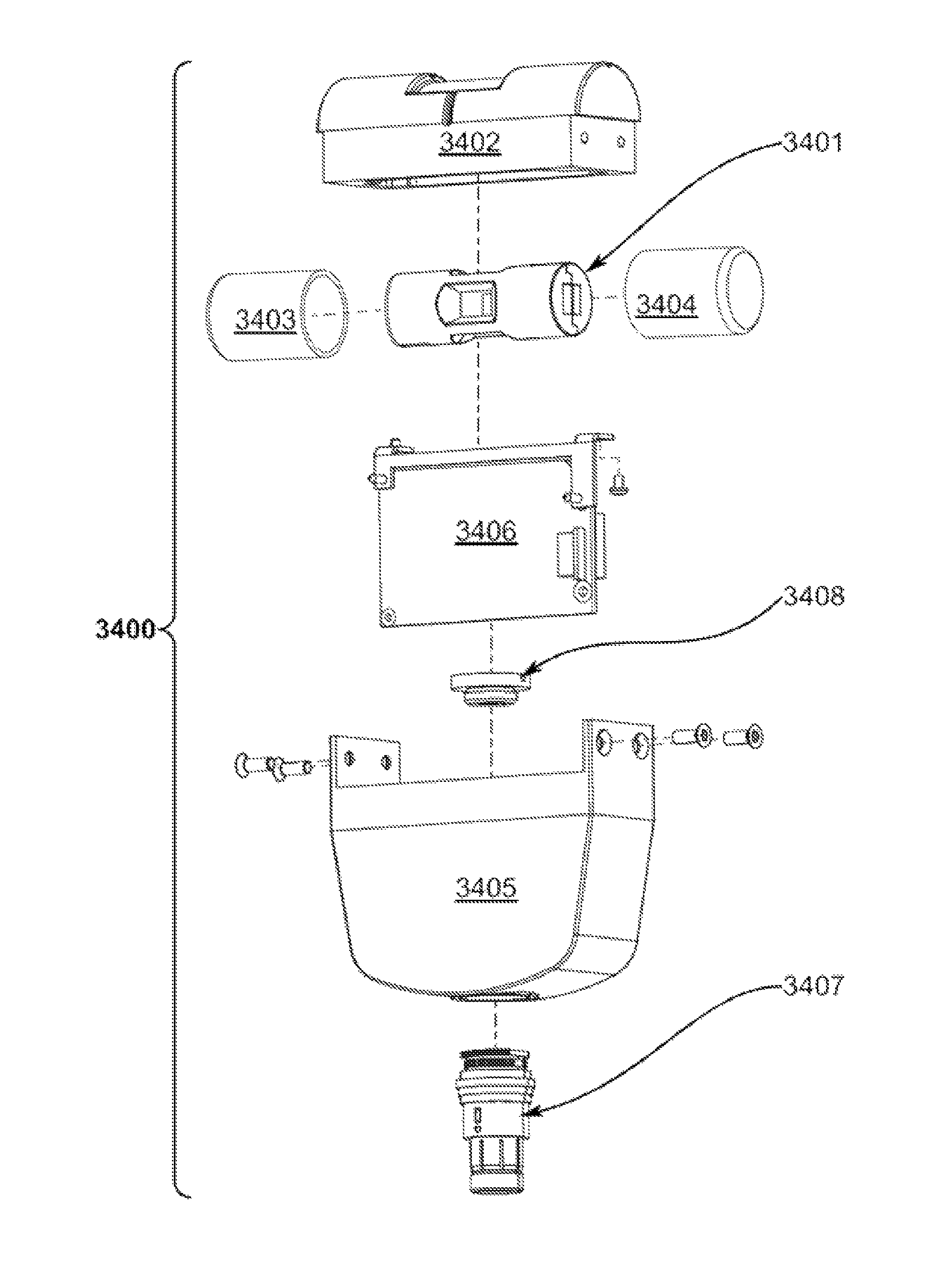
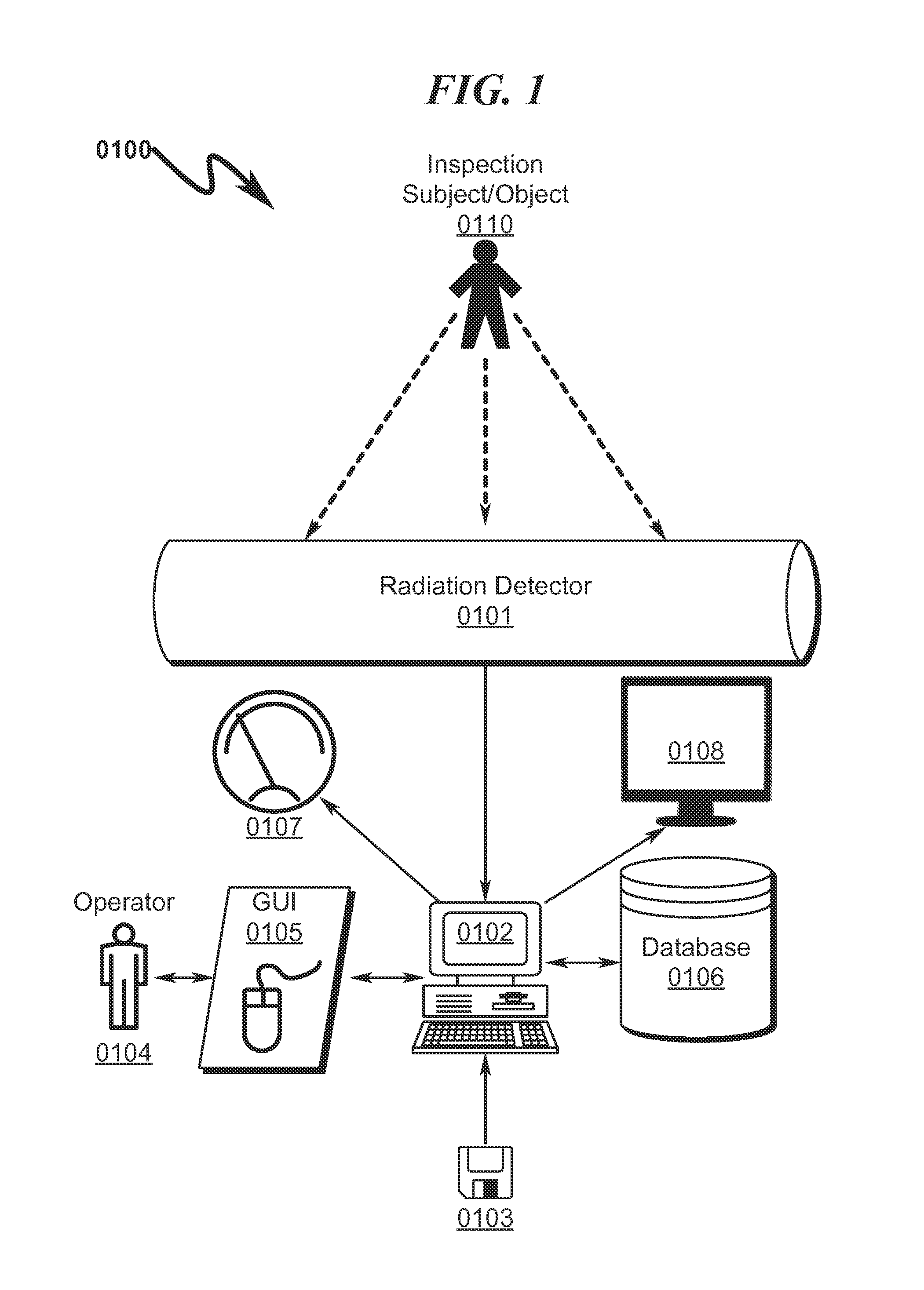
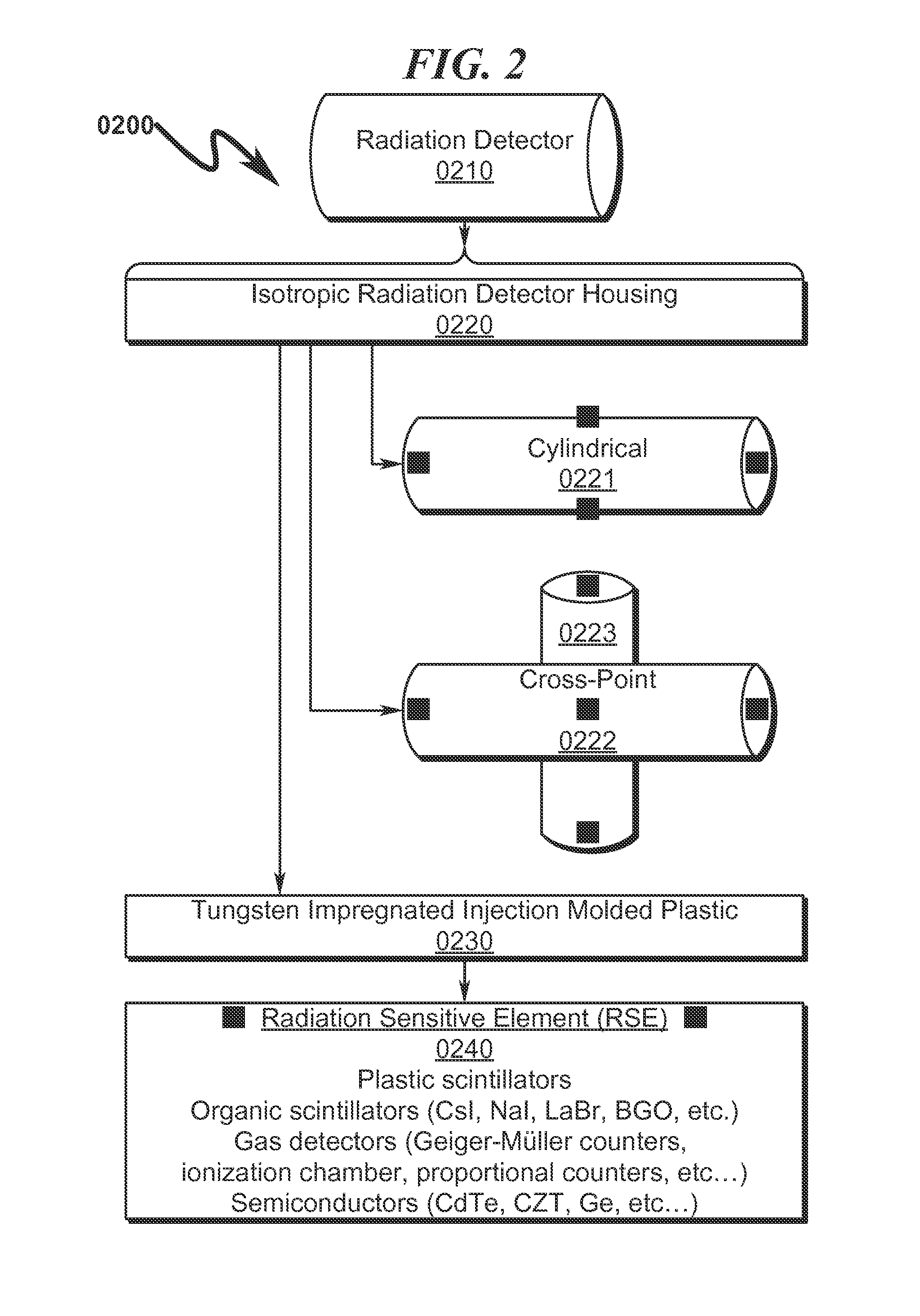
[0301]The present invention preferred exemplary method embodiment anticipates a wide variety of variations in the basic theme of implementation, but can be generalized as a radiation detector method, the method operating in conjunction with a radiation detector system comprising:[0302](a) tubular radiation detector housing (TRDH); and[0303](b) radiation sensitive elements (RSEs);[0304]wherein[0305]the TRDH comprises charged plastic;[0306]the TRDH comprises an outer cylindrical surface;[0307]the TRDH comprises end apertures located at the distal ends of the outer cylindrical surface;[0308]the TRDH comprises one or more circumferential apertures located at approximately the midpoint between the distal ends of the outer cylindrical surface;[0309]the RSEs are responsive to the presence of radiation; and[0310]the RSEs are inset into the end apertures and the circumferential apertures;[0311]wherein the method comprises the steps of:[0312](1) Modifying th...


PUM


Abstract

A radiation detector dosimeter system / method implementing a corrected energy response detector is disclosed. The system incorporates charged (typically tungsten impregnated) injection molded plastic that may be formed into arbitrary detector configurations to affect radiation detection and dose rate functionality at a drastically reduced cost compared to the prior art, while simultaneously permitting the radiation detectors to compensate for radiation intensity and provide accurate radiation dose rate measurements. Various preferred system embodiments include configurations in which the energy response of the detector is nominally isotropic, allowing the detector to be utilized within a wide range of application orientations. The method incorporates utilization of a radiation detector so configured to compensate for radiation counts and generate accurate radiation dosing rate measurements.

Description

CROSS REFERENCE TO RELATED APPLICATIONSContinuation Patent Applications[0001]This application claims benefit under 35 U.S.C. §120 and is a Continuation-in-Part Patent Application and hereby incorporates by reference United States Patent Application for RADIATION DETECTOR SYSTEM AND METHOD, by inventor Olivier Gaëtan Giarmana, U.S. Patent Application No. 13 / 453,024, filed Apr. 23, 2012.Foreign Patent Applications[0002]This application claims benefit under 35 U.S.C. §119 and hereby incorporates by reference French Patent Application for RADIATION DETECTOR SYSTEM AND METHOD by inventor Olivier Gaëtan Giarmana, French Patent Application No. 1254351, filed May 11, 2012.[0003]U.S. patent application Ser. No. 13 / 453,024, filed Apr. 23, 2012 claims benefit under 35 U.S.C. §119 and hereby incorporates by reference European Patent Application for RADIATION DETECTOR SYSTEM AND METHOD, by inventor Olivier Gaëtan Giarmana, European Patent Application No. 12165034.5, filed Apr. 20, 2012.PARTIAL W...

Claims


Application Information

Patent Timeline
Patent Type & Authority Patents(United States)
IPC IPC(8): G01T3/08G01T3/00G01T3/06G01T1/00G01T1/02
CPCG01T3/08G01T7/00G01T3/06G01T1/00G01T1/02G01T1/023G01T1/026
Inventor GIARMANA, OLIVIER, GAETAN
Owner MIRION TECH CANBERRA SAS
Learn More