Bearing, clutch bearing device and motor vehicle equipped with such a clutch bearing device

a technology of clutch bearing and bearing device, which is applied in the direction of mechanical actuated clutches, interlocking clutches, couplings, etc., can solve the problems of compromising the self-centering and sealing functions of the flange, affecting the cost and assembly difficulty and introducing an additional element has a considerable impact on the cost and weight of the clutch bearing devi

Active Publication Date: 2016-04-14
AB SKF
View PDF1 Cites 1 Cited by
  • Summary
  • Abstract
  • Description
  • Claims
  • Application Information

AI Technical Summary

Benefits of technology

[0009]Owing to the invention, the self-centering function of the flange is obtained by the recess provided in the inner ring and the flange provides the sealing function in any operative situation of the device and therefore for any clearance movements of the parts of the device. Because of this solution, the support contact between the inner ring and the metal sleeve can be increased by an extension of the contact surface area, in particular an extension of the radial end of the inner ring. In this way, the contact between the inner ring and the metal sleeve is guaranteed with small cost and without additional elements. Another advantage of the invention is that assembling of the bearing is simple and fast.
[0010]According to further aspects of the invention which are advantageous but not compulsory, such a bearing may incorporate one or several of the following features taken in any admissible configuration:
[0011]The diameter of an inner bore of the flange is greater than or equal to the diameter of the inner bore of the inner ring.
[0012]The recess of the inner ring is radially open towards the inner bore of the inner ring and is provided on an inner surface of the radial end portion of the inner ring.
[0013]The flange includes a flat annular portion inserted in the recess and an external skirt.
[0014]The flange includes a flat annular portion folded over a central portion equipped with the external skirt.

Problems solved by technology

When the contact between these parts is interrupted, because of a clearance movement of the device, the self-centering and sealing functions of the flange are compromised.
However, the insertion of an additional element has a considerable impact on the cost and on the assembling difficulties of the clutch bearing device.
This approach has, however, a negative consequence on the cost and weight of the clutch bearing device.
However, the contact between the inner ring and the metal sleeve is not guaranteed during a clearance movement and the protrusion of the metal sleeve is not adequate for guaranteeing the self-centering function.

Method used


Image

  • Bearing, clutch bearing device and motor vehicle equipped with such a clutch bearing device
  • Bearing, clutch bearing device and motor vehicle equipped with such a clutch bearing device
  • Bearing, clutch bearing device and motor vehicle equipped with such a clutch bearing device

Examples


first embodiment

[0059]FIGS. 5 to 13 partially show several bearings 1 according to alternative embodiments of the invention. The elements of these bearings 1 identical to the corresponding ones of the first embodiment bear the same references and they are not described in detail, insofar as the description here-above can be transposed to these elements.

second embodiment

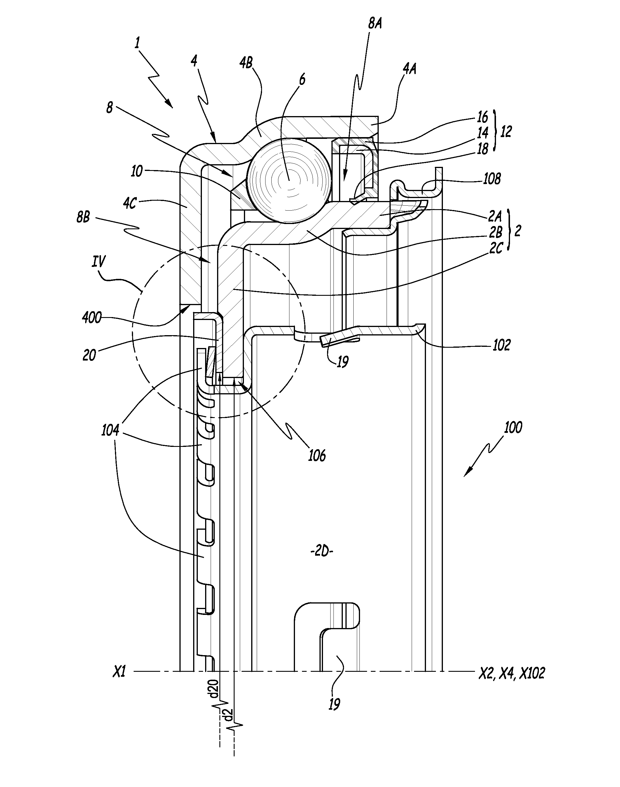
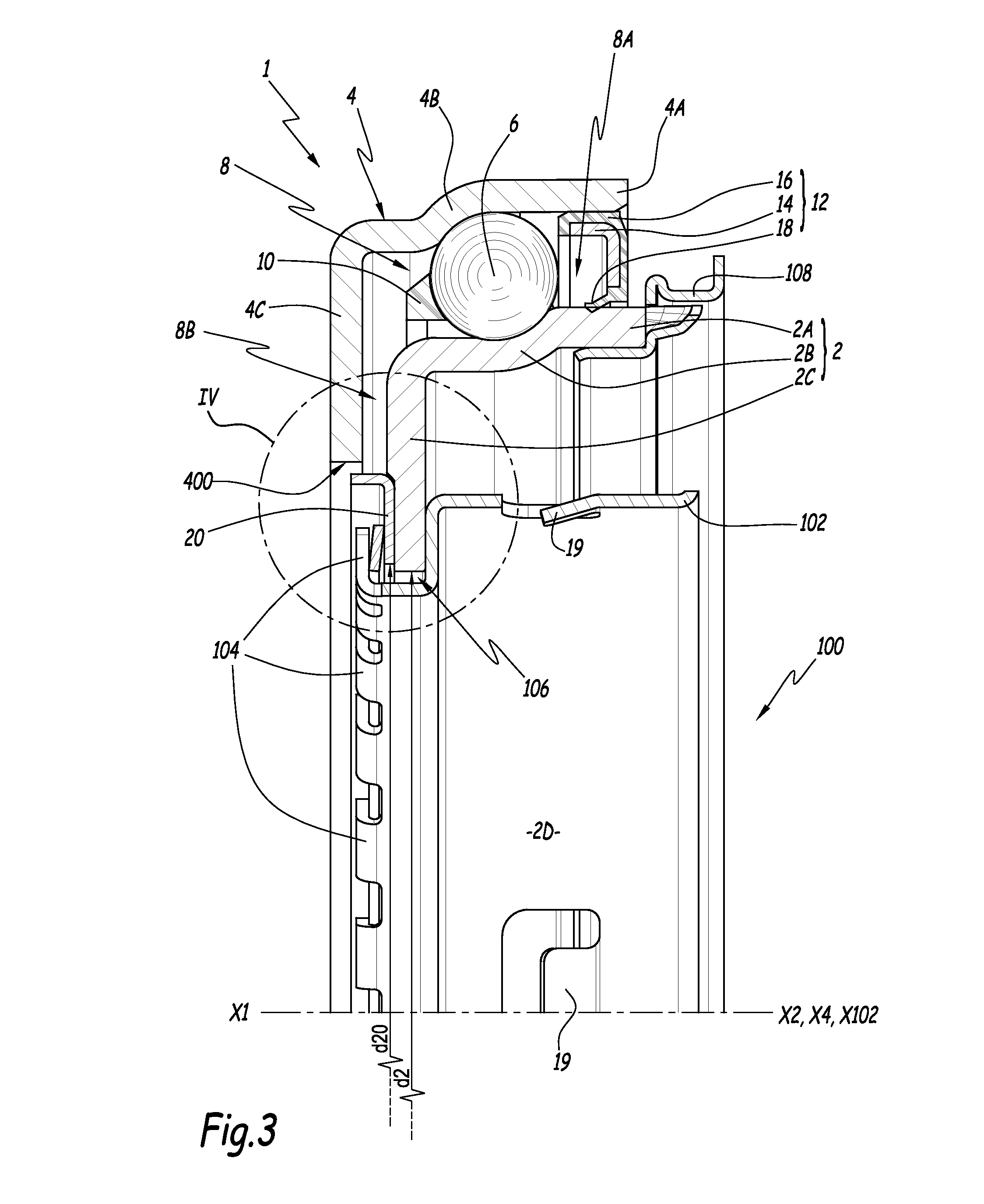
[0060]In the invention, which is shown in FIG. 5, flange 20 includes a flat annular portion 22 which is in contact with floor 203 of recess 210 and which is axially aligned with inclined edge 212. Annular portion 22 is folded over a central portion 30 of flange 20. The transition between central portion 30 and annular portion 22 is performed by a bent portion 31. Bent portion 31 defines the inner diameter d20 of the flange 20. A radial outer edge 220 of annular portion 22 is adjacent to the frustoconical edge 212 of the recess 210. The central portion 30 is equipped with an external skirt 24 and the transition between central portion 30 and skirt 24 is performed by a curved portion 26. The conical ring 28 is in abutment against the central portion 30 of the flange 20.

[0061]In this embodiment also, one has the relationship d20>d2, where d2 is defined as in the first embodiment.

third embodiment

[0062]In the invention, which is shown in FIG. 6, recess 210 is provided with a frustoconical edge 212 between part 205 of inner surface 202 and its floor 203. Flange 20 is provided with a flat annular portion 22, which is in contact with inner surface 202, and with a bent radial inner end 32, which is inserted in recess 210.


PUM


Abstract

A bearing forming a clutching-declutching bearing for a motor vehicle, the bearing defining a central axis and including an outer ring free to rotate around the central axis, an inner ring, rolling elements disposed between the outer ring and inner ring and a flange mounted on the inner ring. The flange is at least partially inserted in a recess which is provided in a radial end portion of the inner ring and which is distinct from an inner bore of the inner ring.

Description

CROSS REFERENCE TO RELATED APPLICATION[0001]This is a Non-Provisional Patent Application, filed under the Paris Convention, claiming the benefit of Europe (EP) Patent Application Number 14306618.1, filed on 13 Oct. 2014 (13.10.2014), which is incorporated herein by reference in its entirety.TECHNICAL FIELD OF THE INVENTION[0002]The present invention relates to a bearing forming a clutching-declutching bearing for a motor vehicle. This invention also relates to a clutch bearing device including a bearing of the above-mentioned type. Finally, this invention relates to a motor vehicle equipped with such a clutch bearing device.BACKGROUND ART OF THE INVENTION[0003]In the automotive industry, it is known to use a bearing comprising an inner ring, an outer ring and rolling elements, arranged in a volume between the rings, for constituting a clutching-declutching bearing and making it possible to control a diaphragm spring which is an example of a declutching mechanism known per se. Such a...

Claims


Application Information

Patent Timeline
Patent Type & Authority Applications(United States)
IPC IPC(8): F16D23/14F16C33/80F16C19/02F16C33/30
CPCF16D23/14F16C19/02F16C33/80F16C33/30F16C19/163F16C2361/43F16D2300/08F16D25/083
Inventor ARNAULT, BENOITWALTER, PHILIPPE
Owner AB SKF
Why Eureka
Try Eureka