Check patentability & draft patents in minutes with Patsnap Eureka AI!

Die cushion device

a technology of die cushion and spherical plate, which is applied in the direction of fluid-pressure actuators, servometer circuits, accumulations, etc., can solve the problems of requiring power costs, complicated devices, and high cost, and achieve the effect of saving power costs and simple and inexpensive die cushion devices

Active Publication Date: 2017-10-10
AIDA ENG LTD
View PDF11 Cites 2 Cited by
  • Summary
  • Abstract
  • Description
  • Claims
  • Application Information

AI Technical Summary

Benefits of technology

The present invention provides a die cushion device that is inexpensive and works efficiently without using a device that consumes electric power. The device uses a pressurized hydraulic fluid system without needing a pump to pressurize and feed the fluid. This results in a simple and cost-effective device that saves power and reduces operating expenses.

Problems solved by technology

That is, since the die cushion device described in PTL 1 requires a compressed air supply source for creating low hydraulic pressure and a hydraulic pump and an electric motor for creating high hydraulic pressure, there is a problem in which the device becomes complicated and expensive.
In addition, there is a problem of requiring power costs (running costs) of driving the compressed air supply source and the electric motor for each cycle of die cushion operation.

Method used


Image

  • Die cushion device
  • Die cushion device
  • Die cushion device

Examples


Embodiment Construction

[0040]With reference to accompanying drawings, embodiments of a die cushion device in accordance with the present invention will be described in detail.

[0041](Configuration of the Die Cushion Device)

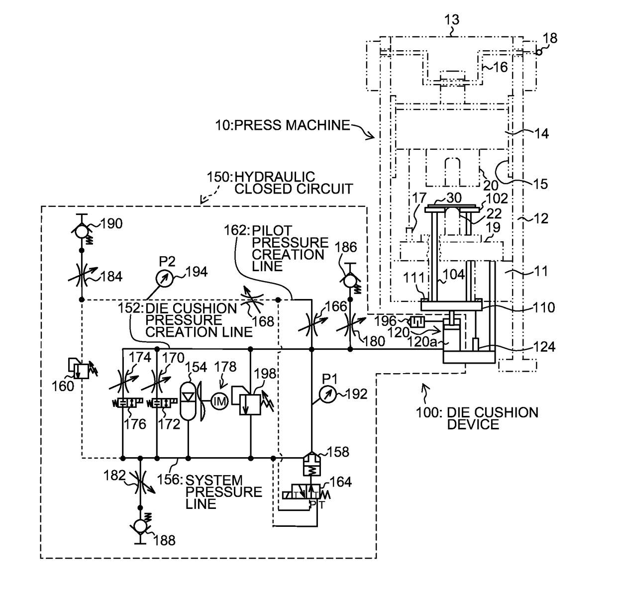
[0042]FIG. 1 is a constitution diagram illustrating an embodiment of a die cushion device in accordance with the present invention. In FIG. 1, a press machine 10 is illustrated with two-dot chain lines and a die cushion device 100 is illustrated with solid lines.

[0043]The press machine 10 illustrated in FIG. 1 includes a frame that is composed of a bed 11, a column 12, and a crown 13, and a slide 14 that is movably guided in a vertical direction by a guide section 15 provided in the column 12. The slide 14 is moved in the vertical direction in FIG. 1 by a servo motor (not illustrated), or a crank mechanism including crankshaft 16 to which rotational driving force is transmitted by a flywheel (not illustrated).

[0044]It is preferable that the press machine 10 is provided on its bed 11 side...


PUM

PropertyMeasurementUnit
hydraulic pressureaaaaaaaaaa
pressureaaaaaaaaaa

Abstract

There is provided a die cushion device that includes a cushion pad, a hydraulic cylinder configured to lift the cushion pad, and a hydraulic closed circuit connected to a die cushion pressure creation chamber of the hydraulic cylinder. The hydraulic closed circuit includes a pilot drive type logic valve that is operable as a main relief valve at the time of the die cushion operation, and a pilot relief valve configured to create pilot pressure for controlling the logic valve. Hydraulic oil is filled in the hydraulic closed circuit, in a pressurized manner, and the hydraulic oil in the hydraulic closed circuit is pressurized by only die cushion force applied from the cushion pad through the hydraulic cylinder, in one cycle period of the cushion pad.

Description

CROSS-REFERENCE TO RELATED APPLICATIONS[0001]The subject application claims priority to Japanese Patent Application No. 2014-120394 filed Jun. 11, 2014, the subject matter of which is incorporated herein by reference in entirety.BACKGROUND OF THE INVENTION[0002]Field of the Invention[0003]The present invention relates to a die cushion device, and more particularly, to an inexpensive and functionally efficient die cushion device.[0004]Description of the Related Art[0005]Heretofore, there is proposed a die cushion device configured to create die cushion pressure by using a balance piston type relief valve (Japanese Patent Application Laid-Open No. 2001-079694, hereinafter referred to as PTL 1).[0006]The die cushion device described in PTL 1 includes, as a device that creates hydraulic pressure to be supplied to a cushion cylinder, a first hydraulic creation mechanism that creates low hydraulic pressure, and a second hydraulic creation mechanism that creates high hydraulic pressure. In...

Claims


Application Information

Patent Timeline
Patent Type & Authority Patents(United States)
IPC IPC(8): B21D24/14B21D24/02F15B21/00F15B1/02
CPCB21D24/14B21D24/02F15B1/024F15B2211/88F15B21/005F15B2211/212
Inventor KOHNO, YASUYUKIKONDO, TADAHIRO
Owner AIDA ENG LTD
Features
  • R&D
  • Intellectual Property
  • Life Sciences
  • Materials
  • Tech Scout
  • Unparalleled Data Quality
  • Higher Quality Content
  • 60% Fewer Hallucinations
Learn More