Die cushion device

a cushion and cushion body technology, applied in the field of die cushion devices, can solve problems such as scratches and cracks that might occur in molded products

Active Publication Date: 2018-08-30
AIDA ENG LTD
View PDF10 Cites 8 Cited by
  • Summary
  • Abstract
  • Description
  • Claims
  • Application Information

AI Technical Summary

Benefits of technology

[0029]According to yet another aspect of the present invention, the first solenoid valve is controlled so as to apply the pilot pressure to the pilot port of the logic valve during the lowering (moving down) period of the cushion pad to enable die cushion pressure corresponding to the pilot pressure to be generated in the die cushion pressure generation line, as well as to enable die cushion force to be generated in the fluid-pressure cylinder during the lowering period of the cushion pad. In addition, the second solenoid valve is opened at an appropriate timing after the die cushion process to enable hydraulic fluid at system pressure accumulated in the accumulator to be supplied to the fluid-pressure cylinder through the die cushion pressure generation line. As a result, it is possible to raise the cushion pad to a standby position.
[0030]According to the present invention, in one process cycle (die cushion lowering process, locking process, raising process), a fluid-pressure pump or an air pressure source or the like that consumes electric power is unnecessary, and locking can be perfectly performed (at or below the slide bottom dead center) when the cushion pad is locked by an inexpensive and functional device without using a special (dedicated) controller.

Problems solved by technology

As described above, in the die cushion device described in Patent Document 1, because the cushion pad rises by around 2 mm from a position of the bottom dead center when the system pressure is released, there is a concern that troubles such as scratches and cracks might occur in a molded product when a thin plate is drawn.

Method used


Image

  • Die cushion device
  • Die cushion device
  • Die cushion device

Examples


Embodiment Construction

[0039]With reference to accompanying drawings, preferred embodiments of a die cushion device according to the present invention will be described in detail.

[0040]

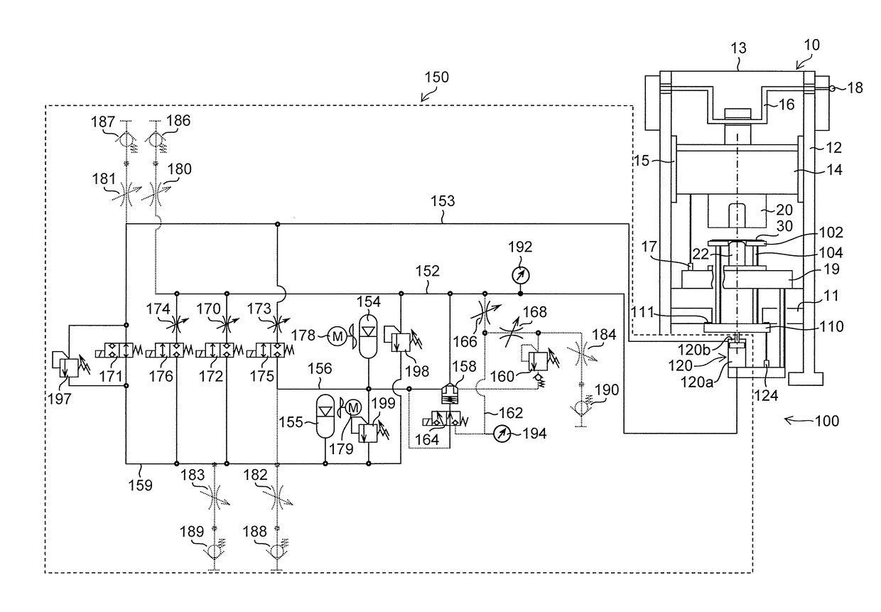
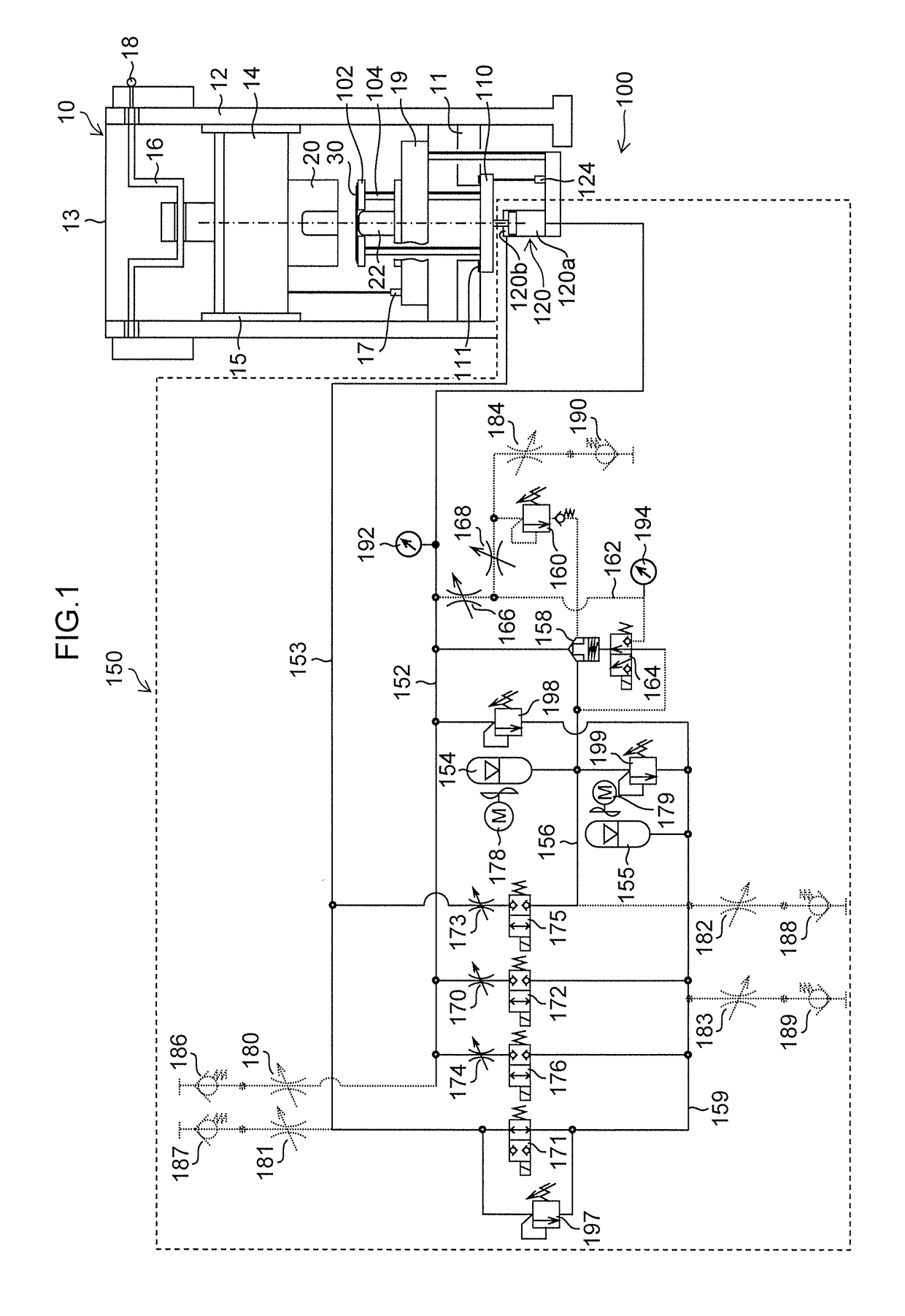
[0041]FIG. 1 is a configuration diagram illustrating an embodiment of a die cushion device according to the present invention when applied to a press machine.

[0042]In the press machine 10 illustrated in FIG. 1, a frame is composed of a bed 11, a column 12 and a crown 13, and a slide 14 is movably guided in a vertical direction by a guide section 15 provided in the column 12. The slide 14 is moved in the vertical direction in FIG. 1 by a servo motor (not illustrated), or a crank mechanism including a crankshaft 16 to which rotational driving force is transmitted by a flywheel (not illustrated).

[0043]It is preferable that the press machine 10 is provided, on its bed 11 side, with a slide position detector 17 that detects a position of the slide 14, or that the crankshaft 16 is provided with a crankshaft encoder 18 that detect...


PUM

PropertyMeasurementUnit
crank angleaaaaaaaaaa
forceaaaaaaaaaa
force Ftaaaaaaaaaa

Abstract

To provide a die cushion device which is inexpensive, functional, and capable of locking completely (at or below the slide bottom dead center). The die cushion device includes a cushion pad, a hydraulic cylinder that moves the cushion pad up and down, and a hydraulic closed circuit connected to a die cushion pressure generation chamber of the hydraulic cylinder. The hydraulic closed circuit includes a cushion pad lowering pressure generation line and a second system pressure line in addition to a die cushion pressure generation line and a first system pressure line. When the cushion pad is locked at the bottom dead center, the cushion pad lowering pressure generation chamber is connected to the first system pressure line, and the die cushion pressure generation chamber is connected to the second system pressure line such that the cushion pad is held at or below the slide bottom dead center.

Description

CROSS-REFERENCE TO RELATED APPLICATIONS[0001]The present application claims priority under 35 U.S.C. § 119 to Japanese Patent Application No. 2017-035058, filed on Feb. 27, 2017. The above application is hereby expressly incorporated by reference, in its entirety, into the present application.BACKGROUND OF THE INVENTIONField of the Invention[0002]The present invention relates to a die cushion device, and more particularly to an inexpensive and functionally efficient die cushion device.Description of the Related Art[0003]Conventionally, as an inexpensive and functional die cushion device, a die cushion device has been proposed in Japanese Patent Application Laid-Open No. 2016-407 (hereinafter referred to as Patent Document 1).[0004]The die cushion device includes a cushion pad, a hydraulic cylinder for moving the cushion pad up and down, and a hydraulic closed circuit connected to a die cushion pressure generation chamber of the hydraulic cylinder. The hydraulic closed circuit has: a...

Claims


Application Information

Patent Timeline
Patent Type & Authority Applications(United States)
IPC IPC(8): B21D24/02
CPCB21D24/02B30B15/02B30B15/16
Inventor KOHNO, YASUYUKI
Owner AIDA ENG LTD
Why Eureka
Try Eureka