Rotary input operation device

a technology of operation device and rotary input, which is applied in the direction of mechanical control device, process and machine control, instruments, etc., can solve the problems of complicated manufacturing process and large scale, and achieve the effects of improving the rotational balance of the rotating operation body, high durability, and smooth rotation

Active Publication Date: 2017-10-17
ALPS ALPINE CO LTD
View PDF10 Cites 2 Cited by
  • Summary
  • Abstract
  • Description
  • Claims
  • Application Information

AI Technical Summary

Benefits of technology

[0013]According to this configuration, the cam part has the plurality of cam faces in which angles between the cam faces and a direction in which the elastic force acts are different from each other, and therefore, due to the different angles, different click feelings can be realized with a small number of parts by a pair of engagement parts and the cam part. For this reason, a reduction in scale and simplification of a manufacturing process can be attained.
[0015]According to this configuration, a click feeling generation function according to a rotating operation and an automatic return function in a case where a rotating operation force is released can be realized by a pair of engagement parts and the cam part, and therefore, the number of parts can be reduced.
[0017]According to this configuration, the angle of the fourth cam face which is close to the maximum rotation angle is small, and therefore, a strong rotating operation force is required at the portion, and proximity to the maximum rotation angle can be transmitted as a sense of an operator's finger. Further, a strong rotating force toward the first cam face is generated in the vicinity of the maximum rotation angle, whereby a return operation when a rotating operation is released can be performed at high speed.
[0019]According to this configuration, a rotating operation force at the maximum rotation angle becomes the maximum, and thus a return operation can be performed at high speed.
[0021]According to this configuration, it is possible to stably position the movable contact at the position of the fixed contact.
[0023]According to this configuration, a rotational balance of a rotating operation body is improved, and thus the rotating operation body can smoothly rotate, and a load to each member is dispersed, thereby being able to exhibit high durability.

Problems solved by technology

However, in the rotary input operation device of the related art described above, the spring for generating a click feeling and the spring for self-return are individually provided, and therefore, there is a problem in that the number of parts is increased, thereby causing a larger scale, and a manufacturing process is complicated.

Method used


Image

  • Rotary input operation device
  • Rotary input operation device
  • Rotary input operation device

Examples


first operation example

[0077]In this operation example, an operation of adjusting the brightness of a headlight will be described.

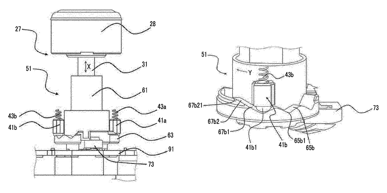
[0078]An operator rotationally operates the rotating operation part 28 shown in FIG. 3 with the fingers or the like. Then, if the rotating operation body 51 rotates, the convex portions 41a1 and 41b1 of the engagement parts 41a and 41b slide in a state of being pressed against the first cam faces 65a and 65b of the cam part 63, whereby a rotational load according to the concavities and convexities of the first cam faces 65a and 65b is transmitted to the fingers or the like of the operator as a click feeling through the rotating operation part 28.

[0079]Further, the engagement parts 41a and 41b are held by the valley portions of the first cam faces 65a and 65b corresponding to the rotational position of the rotary input operation device 27, and the movable contact electrode 75 comes into contact with the fixed contact electrode 111 corresponding thereto. Then, the rotational posi...

second operation example

[0080]In this operation example, an operation of turning on and off an automatic function of a headlight will be described.

[0081]An operator rotationally operates the rotating operation part 28 shown in FIG. 3 with the fingers or the like to the vicinity of the maximum rotational positions of the end portions 67a21 and 67b21 of the second cam faces 67a and 67b in a direction of an arrow Y shown in FIG. 6.

[0082]In this way, the movable contact electrode 75 comes into contact with the fixed contact electrode 111 corresponding to the maximum rotational position. Then, a rotational position is detected by an electrical signal which is generated according to the contact position, and the automatic function of the headlight is switched on and off.

[0083]Here, in a state where the rotating operation body 51 is in the vicinity of the maximum rotational position, that is, the engagement parts 41a and 41b are pressed against the fourth cam faces 67a2 and 67b2, the engagement parts 41a and 41b ...


PUM


Abstract

In a rotating operation body, a cam part has first cam faces for click feeling generation and second cam faces for return of the rotating operation body. The second cam faces are respectively formed continuously with the first cam faces, and an angle between each of the second cam faces and a direction in which elastic forces of engagement parts are generated is smaller than an angle of each of the first cam faces. That is, each of the second cam faces has a steeper slope than each of the first cam faces.

Description

CLAIM OF PRIORITY[0001]This application claims benefit of Japanese Patent Application No. 2015-083532 filed on Apr. 15, 2015, which is hereby incorporated by reference.BACKGROUND OF THE INVENTION[0002]1. Field of the Invention[0003]The present invention relates to a rotary input operation device which performs input according to a rotating operation, and an input operation system which uses the rotary input operation device.[0004]2. Description of the Related Art[0005]There is a rotary input operation device in which input instructions corresponding to a rotation angle are performed by rotating a rotating operation part with the fingers or the like and a rotation return force is generated if a rotation angle of the rotating operation part exceeds a certain angle, and which has a self-return function of automatically returning to the original position when a rotating operation is released.[0006]In such a rotary input operation device, a spring for generating a click feeling and a spr...

Claims


Application Information

Patent Timeline
Patent Type & Authority Patents(United States)
IPC IPC(8): G05G1/10G05G5/06G05G1/08
CPCG05G1/08G05G1/10G05G5/06G05G5/04G05G5/05
Inventor KONNO, SATORUCHOI, YEONJO
Owner ALPS ALPINE CO LTD
Why Eureka
Try Eureka