Modularly redundant DC-DC power supply arrangement having outputs that can be connected in parallel

a power supply arrangement and modular technology, applied in emergency power supply arrangements, electrical energy, instruments, etc., can solve the problems of excessive losses, one of the two supply units will have a shorter service life, and the two supply units will wear and tear even after being used. to achieve the effect of overvoltage protection

Active Publication Date: 2017-10-17
SIEMENS AG
View PDF10 Cites 3 Cited by
  • Summary
  • Abstract
  • Description
  • Claims
  • Application Information

AI Technical Summary

Benefits of technology

[0010]The redundant power supply arrangement according to the present invention is implemented as a device having two parallel paths, each of which comprises two converter stages. This eliminates the requirement to decouple the outputs using a redundancy circuit. It also ensures favorable component loading while minimizing the structural size and the losses that occur. The cabling costs are also reduced in comparison with known solutions.
[0032]In this case, a warning signal is generated in the decoupling mode as soon as a current flow direction from an output to an input of a respective output switching controller is detected and / or a set maximum current value is reached, and / or if a maximum permitted output voltage is reached in an overvoltage protection mode. In this way, an operator is quickly made aware of a fault.

Problems solved by technology

This results in uneven wear of the two supply units, whereby it can be assumed that one of the two units will have a shorter service life.
Diodes result in excessive losses when higher powers are supplied.
Here, likewise, the wear of the two supply units is uneven, because only that supply unit connected to a load via the switch is under load during normal operation.
Moreover, a brief interruption of supply occurs during a switchover operation in the event of a fault.

Method used


Image

  • Modularly redundant DC-DC power supply arrangement having outputs that can be connected in parallel
  • Modularly redundant DC-DC power supply arrangement having outputs that can be connected in parallel
  • Modularly redundant DC-DC power supply arrangement having outputs that can be connected in parallel

Examples


Embodiment Construction

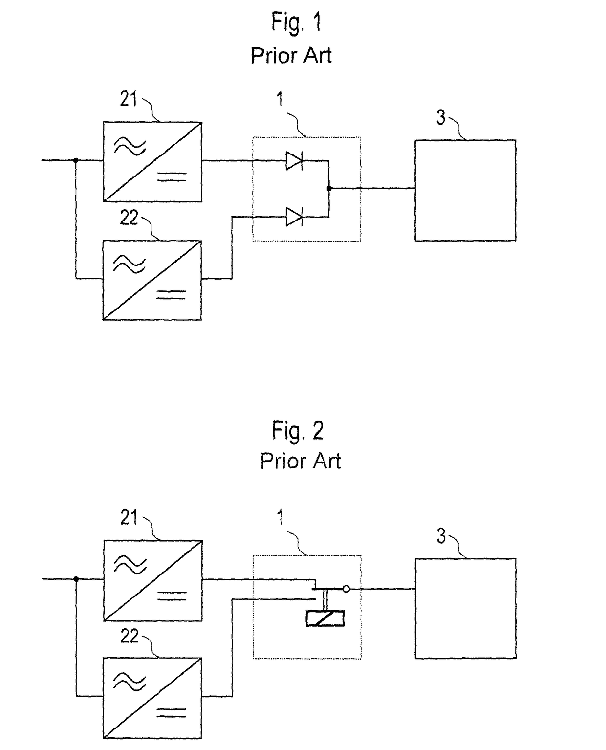
[0043]FIGS. 1 and 2 show redundant power supply arrangements as per the prior art. In this case, a redundancy circuit 1 coupled to a load 3 is connected to two separate supply units 21, 22. Each of these supply units 21, 22 represents a separate power supply device.

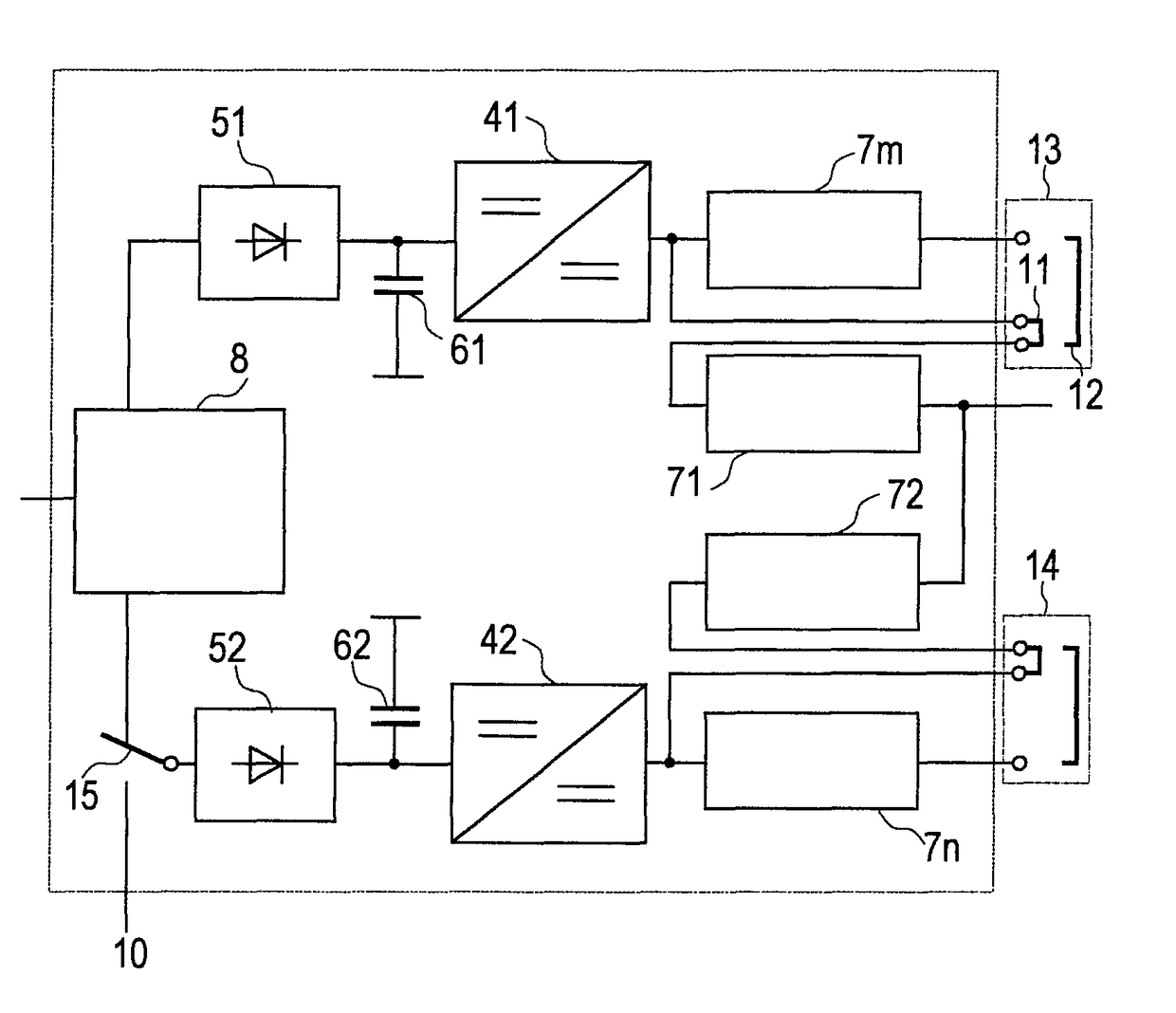
[0044]By contrast, according to the present invention, a power supply arrangement for redundantly supplying power to a load is adapted as a single device in a housing, wherein components not relevant to safety are included only once.

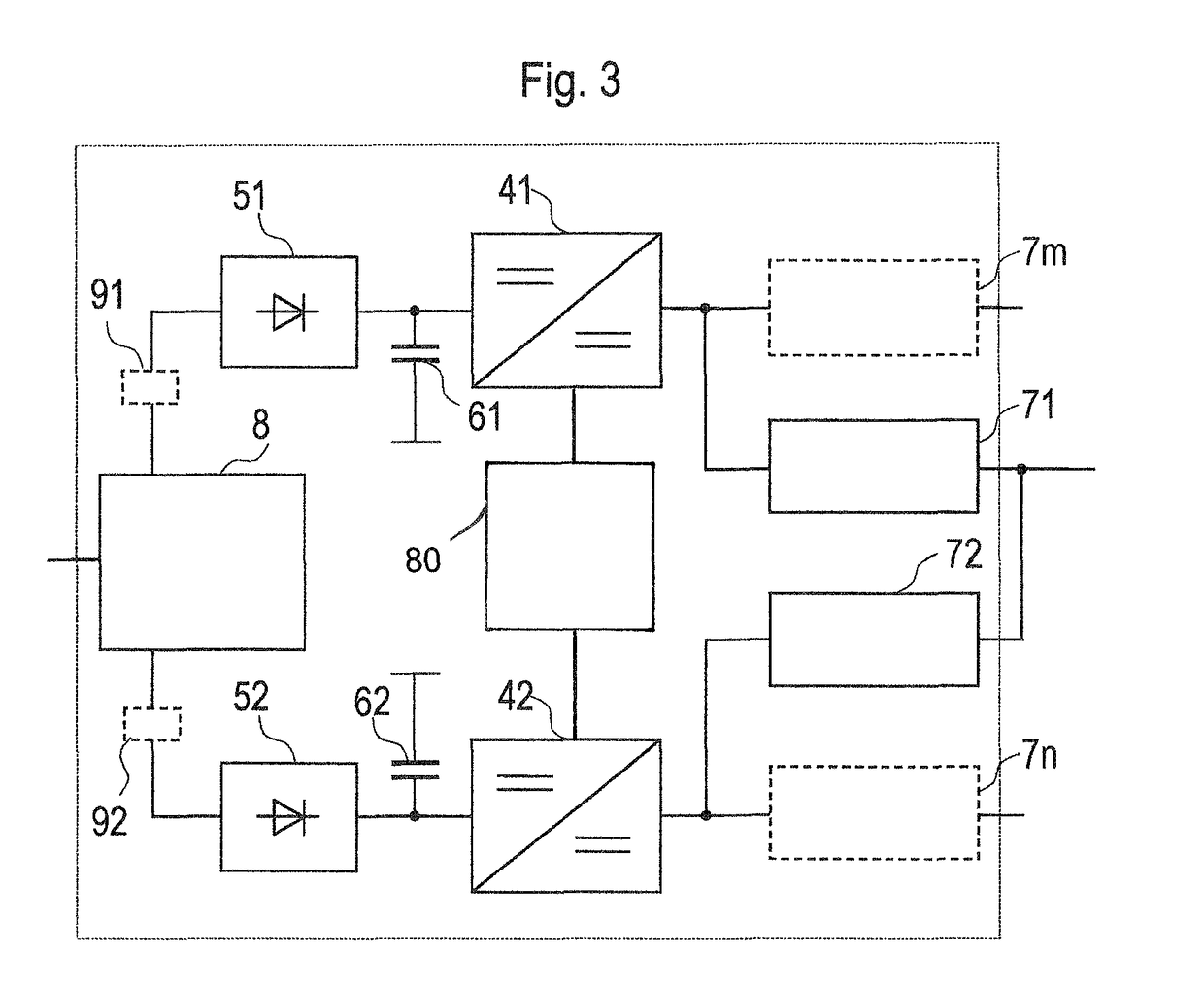
[0045]As shown in FIG. 3, a power supply arrangement in accordance with one embodiment comprises only one passive filter 8, via which two paths are connected to a supply network. Each path comprises a rectifier unit 51 or 52, a DC link with capacitor 61 or 62, a DC-DC converter 41 or 42 and at least one output switching controller 71 or 72. A plurality of output switching controllers 71, 7m or 72, 7n can also be connected to each DC-DC converter 41 or 42, respectively.

[0046]A protection unit 9...


PUM


Abstract

A power supply device for redundantly supplying power to a load comprises a first supply unit, a second supply unit, a first DC-DC converter, a second DC-DC converter, a first output switching controller, and a second output switching controller. The first and second supply units are interconnected. The first output switching controller is connected on the load side of the first DC-DC converter, and the second output switching controller is connected on the load side of the second DC-DC converter. The outputs of the output switching controllers are interconnected.

Description

CROSS-REFERENCE TO RELATED APPLICATIONS[0001]This is U.S. national stage of PCT Application No. PCT / EP2013 / 050621, filed on Jan. 15, 2013, which claims priority to European Patent Application No. EP 12153970.4, filed on Feb. 6, 2012, each of which is hereby incorporated herein in its entirety by reference.FIELD OF INVENTION[0002]The invention relates to a power supply arrangement for redundantly supplying power to a load, wherein the power supply arrangement comprises a first supply unit and a second supply unit that are interconnected.DESCRIPTION OF THE RELATED ART[0003]Electrical installations are often governed by particular safety requirements or the need for high availability. Critical parts of such installations are implemented to offer redundancy in order to prevent failure of the installation if a fault occurs. This also relates to power supply arrangements.[0004]According to the prior art, a redundant power supply arrangement includes two separate supply units whose outputs...

Claims


Application Information

Patent Timeline
Patent Type & Authority Patents(United States)
IPC IPC(8): H02J1/10H02M3/158H02M3/335H02J9/06H02M1/00
CPCH02J1/102H02J1/10H02M3/158H02M3/1584H02J9/06H02M3/33523H02M2001/007Y02B70/1425Y02B70/1433Y02P80/112H02M1/007Y02B70/10Y02P80/10
Inventor AUGESKY, CHRISTIANSCHWEIGERT, HARALD
Owner SIEMENS AG
Why Eureka
Try Eureka