Hitch clip lockable safety cover

a safety cover and latching technology, applied in the field of safety covers, can solve the problems of removing the latching pin and the latching pin, and achieve the effects of ensuring the safety of the hitch assembly, easy access, and not easy to remov

Inactive Publication Date: 2017-10-24
BUCKNER JAMES A
View PDF10 Cites 1 Cited by
  • Summary
  • Abstract
  • Description
  • Claims
  • Application Information

AI Technical Summary

Benefits of technology

[0008]When assembled with the hitch assembly, the safety device is integrated with the hitch pin of the hitch assembly. In one embodiment, the fifth and sixth apertures are slidably received over the hitch pin, and then the retainer pin is slidably engaged within the first channel, thereby securing the cover member between the receiver / hitch member and the retainer pin. The cover member is then revolved about the hitch pin to a position that results in the first and second planar members covering the retainer pin. A loop within the retainer pin may be coaxially aligned with the fifth and sixth apertures such that a locking device may be inserted through the loop and the fifth and sixth apertures. In this way, the retainer pin is locked and easy access to the retainer pin is prevented, thereby ensuring that the retainer pin is not easily removed, and also ensuring that the security of a load on the hitch assembly, such as a trailer, is relatively assured.

Problems solved by technology

One challenge with this type of design is that if left unattended, the hitch pin may be removed if not locked in place.
If, however, the cotter pin is removed, the possibility exists that the hitch pin might either be removed, or, that the hitch pin might over time vibrate to place the hitch in an unsecured state.
Furthermore, certain hitch assemblies containing a hitch and a receiver are not securable and therefore may permit the theft of unauthorized release of a load that is otherwise attached to an associated vehicle.

Method used


Image

  • Hitch clip lockable safety cover
  • Hitch clip lockable safety cover
  • Hitch clip lockable safety cover

Examples


first embodiment

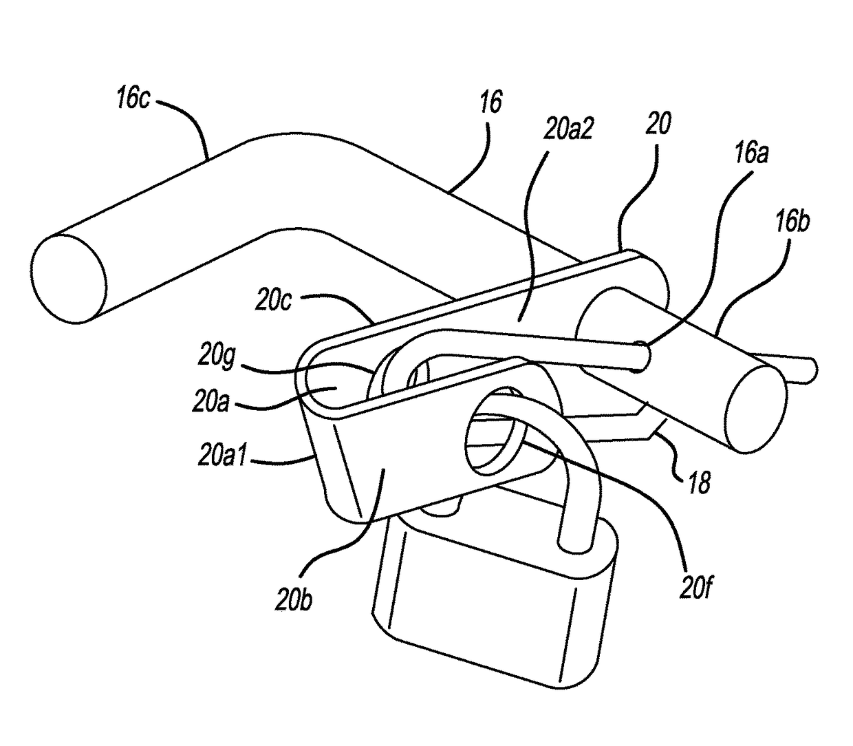
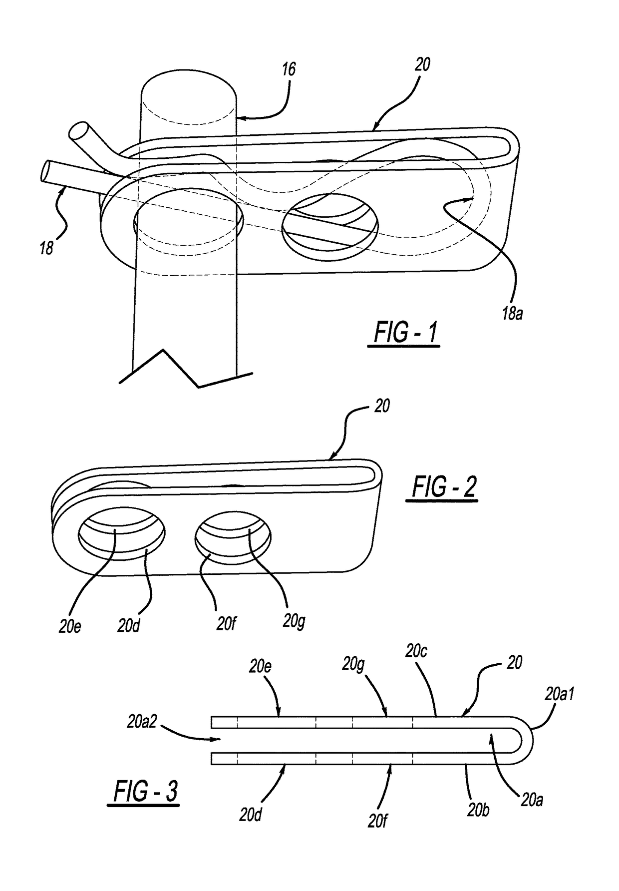
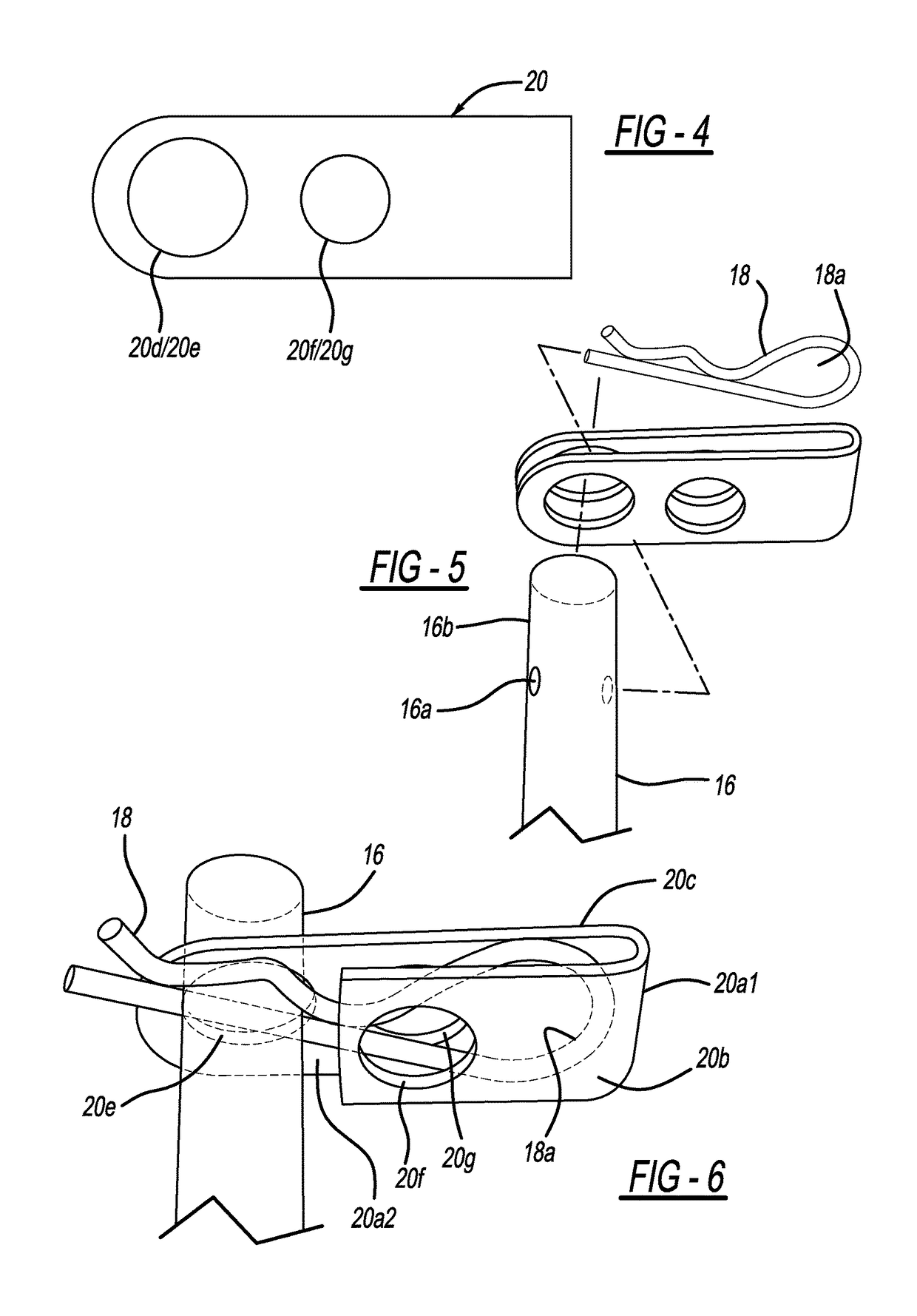
[0030]In a first embodiment, a perforate hitch clip or cover member 20 is adapted to slidably engage over exterior portion 16b of the hitch pin 16. A gap 20a having a closed end 20a1 and an open end 20a2, is formed between two overlying arms or planar members 20b / 20c of the cover member 20. In this embodiment, a fifth aperture 20f is formed in a first planar member 20b and a sixth aperture 20g is formed in a second planar member 20c of the cover member 20, such that the fifth and sixth apertures 20f and 20g are substantially coaxially aligned. At least one additional aperture, a seventh aperture 20d is formed in the first planar member 20b and is respectively spaced from the fifth aperture 20f. If desired, an eighth aperture 20e may be formed in the second planar member 20c spaced apart from the sixth aperture 20g, whereby seventh aperture 20d is coaxially aligned with eighth aperture 20e, if the eighth aperture 20e is formed in the second planar member 20c. As shown in FIGS. 6 and ...

second embodiment

[0033]In a second exemplary embodiment shown in FIG. 11, and as also described above, a first cover 20 may be provided at a first end 16b of the hitch pin 16. A first perforate hitch clip or cover member 20′ is adapted to slidably engage over first end or exterior portion 16b of the hitch pin 16. A first gap 20a having a first closed end 20a1 and a first open end 20a2, is formed between two overlying planar members 20b / 20c of the cover member 20. In this second embodiment as well, a fifth aperture 20d is formed in the first planar member 20b and a sixth aperture 20e is formed in the second planar member 20c of the cover member 20, such that the fifth and sixth apertures 20d and 20e are substantially coaxially aligned. At least one additional aperture, a seventh aperture 20f is formed in the first planar member 20b and is respectively spaced from the fifth aperture 20d. As indicated in FIG. 11, for example, the first planar member 20b may be longer in length than the second planar me...


PUM


Abstract

A safety device 100 for a hitch assembly 10 is provided, the safety device 100 containing a cover member or hitch clip 20 for securing a retainer pin 18 of the hitch assembly 10.

Description

TECHNICAL FIELD[0001]The present invention relates generally to a safety cover for a hitch assembly that enhances the safety of the hitch assembly by means of a locking system.BACKGROUND OF THE INVENTION[0002]The present invention relates to a device for securing a tow hitch to the receiver on a vehicle. In many instances, a tow hitch may be received within a female channel or receiver on a vehicle. Typically, the hitch is secured by coaxially aligning a pair of holes in the sides of the receiver with a second pair of holes in the hitch. As the male member or hitch is slidably received within the female member or receiver, the holes are aligned and then a hitch pin is inserted within the holes.[0003]One challenge with this type of design is that if left unattended, the hitch pin may be removed if not locked in place. At least one cotter pin or retention pin is typically used to secure the hitch pin within both the receiver and the hitch. If, however, the cotter pin is removed, the p...

Claims


Application Information

Patent Timeline
Patent Type & Authority Patents(United States)
IPC IPC(8): B60D1/28B60D1/52B60D1/60
CPCB60D1/605B60D1/52B60D1/025
Inventor BUCKNER, JAMES A.
Owner BUCKNER JAMES A
Why Eureka
Try Eureka