Internal cooling of engine components

a technology of internal cooling and components, which is applied in the direction of machines/engines, stators, mechanical equipment, etc., can solve the problems of affecting the life of uncooled turbines, affecting the efficiency of the engine, and the cooling air from the compressor used to cool the hot turbine components is not used fully to extract work from the turbin

Inactive Publication Date: 2017-10-24
ROLLS ROYCE PLC
View PDF7 Cites 15 Cited by
  • Summary
  • Abstract
  • Description
  • Claims
  • Application Information

AI Technical Summary

Benefits of technology

[0023]It is thus a primary object of the present invention to ameliorate or at least partially solve at least some of the shortcomings of the above prior art cooling arrangements and to provide an improved design of engine component in which a desired pressure margin between the feed pressure of the cooling air entering the key parts of the component and the pressure of the gas-path is more readily and assuredly maintainable.
[0052]In some embodiments it may be possible for the partitioning element to be shaped and / or configured so that it directs the airflow impinging on it in one or more particular directions which may be desirable from a cooling optimisation standpoint. For instance, by aligning the airflow in the defined sub-chamber, adjacent the aerofoil leading edge portion, with the showerhead holes (where provided) fed by this sub-chamber, the dynamic head of pressure may also be used to boost the effective feed pressure of the airflow actually effecting the cooling.
[0066]By implementation of the present invention various advantages may be attainable in comparison with operating a corresponding internally cooled engine component which does not include the characteristic partitioning element(s) as defined above. In particular the maintenance of a desired or optimum backflow pressure margin between the feed pressure of the cooling air entering the relevant cooling chamber(s) adjacent the leading edge of the component and the pressure of the gas-path is more readily and assuredly maintainable within a desired range or limits. Not only may this lead to improved cooling of the leading edge portion of the component, but as an important consequence of this it may further lead to one or more other advantages, including:
[0068]enabling a reduction in the local thickness of the component, especially the thickness of the aerofoil section in cases where the component is an NGV or other aerofoil-shaped component;
[0069]enabling use of the resulting additional cooling air feed pressure to increase the local internal heat transfer at the leading edge of the component.
[0070]Any of the above advantages, either singly or in any combination, may lead to overall improved efficiency and performance of the engine, which may for instance manifest itself ultimately in reduced specific fuel consumption, as well as perhaps other benefits.

Problems solved by technology

However as turbine entry temperatures increase, the lifespan of an uncooled turbine falls, necessitating the development of better materials and the introduction of internal air cooling for many of its components.
HP turbine nozzle guide vanes (NGVs) in particular consume the greatest amount of cooling air in high temperature engines.
The cooling air from the compressor that is used to cool the hot turbine components is not used fully to extract work from the turbine.
Extracting coolant flow therefore has an adverse effect on the engine operating efficiency.
However, the increased coolant flow levels required to accommodate these changes in local gas temperature have a detrimental effect on the local feed pressure supplying the internal cooling holes of the NGV aerofoils 3.
The last ˜10 years has seen a significant rise in the inlet gas temperature and overall engine pressure ratio in newer engine designs, and this has brought a new raft of problems in the turbine section of the engine.
The turbine life is typically limited by the lives of the hot section aerofoil components.
However the pressure ratio across these cooling holes is not very high, and therefore under some engine conditions there is a danger of hot gas ingestion into at least the forward cooling cavity of the NGV.
If this occurs then the consequences can be disastrous, owing to the resulting failure to provide the necessary cooling.
These known designs of NGV aerofoil cooling arrangements all suffer from various problems, shortcomings or limitations.
For example:Higher gas temperatures experienced by the NGV aerofoils result in higher coolant flow requirements.
Dual-end feed forward cooling chambers have proved beneficial to some extent in keeping the inlet velocity (Mach no.) down to relatively low levels, but these improvements have already been offset by the increased flow demands, so any further improvement based on such features is limited.“Bell-mouthed” entrance shapes have also played a useful part in keeping the local inlet velocity (Mach no.) at a low level by eliminating or reducing inlet separation, but again this feature only gives limited improvements.According to current knowledge in the art, the only ways that remain for the designer to ensure that the cooling chamber feed pressure is kept at a safe level above that in the gas-path is to accommodate the increased flow requirements by designing a “fatter” aerofoil shape at the root or tip sections thereof, in order to increase the inlet flow area of the forward cooling chamber, or to increase the pressure drop across the combustor (P30-P40).
However, both such design changes would seriously affect the efficiency of the turbine or cycle of the engine.

Method used


Image

  • Internal cooling of engine components
  • Internal cooling of engine components
  • Internal cooling of engine components

Examples


first embodiment

[0093]In its simplest form, the invention is shown in FIGS. 5(a) and 5(b), which show diagrammatically the geometry of the new arrangement according to this embodiment. Mounted within the inlet portion of the chamber 103F is a partitioning element 100, which is in the form of a curved, arcuate or scoop-shaped plate or sheet (e.g. of the same or a compatible metal or alloy as used to cast the NGV side walls). The new partitioning element 100 divides the inlet portion of the cooling chamber 103F into two sub-chambers: a primary sub-chamber 150 which is located forwardly immediately adjacent the leading edge portion of the NGV (and thus adjacent the stagnation zone 80) and a secondary, rearward located, sub-chamber 160 which carries the remainder of the cooling air feed into the cooling chamber 3F. A sheet metal (e.g. planar) baffle plate 170 is located slightly below mid-span within the cooling chamber 3F. As shown schematically in FIG. 5(a), the partitioning element 100 extends a sho...

second embodiment

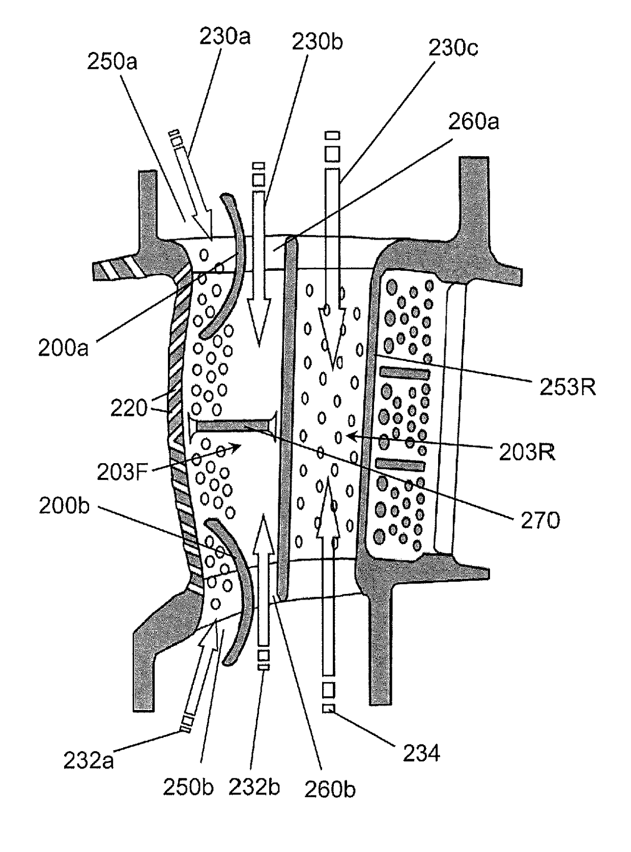
[0105]FIGS. 6(a), 6(b) and 6(c) show the invention, in which a HPT NGV aerofoil cooling arrangement comprises a dual-end cooling air feed supplying cooling air from both outboard 230 and inboard 232, 234 sources to the forward cooling chamber 203F. Mounted generally centrally within and across the width of the chamber 203F is a planar baffle plate 270. Mounted within the rear cooling chamber 203R is impingement plate 253R, adjacent the rear suction-side side wall of the rear chamber 203R. A first partitioning element 200a is provided in the outboard inlet portion of the forward chamber 203F (i.e. that fed from the outboard cooling air feed source 230) and a second partitioning element 200b is provided in the inboard inlet portion of the forward chamber 203F (i.e. that fed from the inboard cooling air feed source 232). Each partitioning element 200a, 200b thus defines a respective forward sub-chamber 250a, 250b, which are fed from, respectively, outboard 230a and inboard 232a sources...

third embodiment

[0109]FIG. 7 shows a third embodiment, which is a HPT NGV aerofoil cooling arrangement with a dual-end feed to a sheet metal insert tube 385a fitted into the forward cooling chamber 303F. There are provided an array of impingement holes in the leading edge wall of the insert tube 385a. The insert tube 385a also has a sheet metal (e.g. planar) baffle plate 370 located slightly below mid-span. The insert tube 385a is mounted in the forward cooling chamber 303F and supported therein by pin-fins 381 (like those labelled 481 in the alternative embodiment of FIG. 8) cast onto the internal walls of the NGV casting. Cooling air enters the insert tube 385a from one or both ends (inboard and / or outboard) and is then bled through an array or series of rows of holes in the insert tube 385a, impinging onto the internal walls of the casting, where the pin-fins 481 provide additional turbulent mixing of the cooling air. The cooling air then passes out of the various internal cooling sub- and mini-...


PUM


Abstract

A gas turbine engine component, especially an aerofoil-sectioned nozzle guide vane (NGV), having at least one internal cooling chamber for passage of cooling air, the chamber including leading edge portion and one inlet portion via which cooling air may enter the chamber from feed source, wherein the component includes a partitioning element, e.g. curved or scoop-shaped partitioning plate or wall, provided in the chamber inlet portion and defining within the inlet portion a sub-chamber adjacent the leading edge portion, and wherein partitioning element is configured so the cooling air velocity in the sub-chamber is less than the cooling air velocity in the remainder of inlet portion. The reduced velocity of the cooling air in the sub-chamber adjacent the leading edge serves to increase pressure therein, thereby maintaining desired backflow pressure margin between the feed pressure of the cooling air delivered to the showerhead holes and the gas-path from the combustor.

Description

TECHNICAL FIELD[0001]This invention relates to the internal cooling of components in an engine, especially a gas turbine engine. More particularly, though not exclusively, the invention relates to improvements in the flow characteristics of cooling air fed into such engine components by modifying the geometry of the cooling air feed arrangement.BACKGROUND OF THE INVENTION AND PRIOR ART[0002]In gas turbine engines the performance of the basic engine cycle, whether measured in terms of efficiency or specific output, is improved by increasing the turbine gas temperature. It is therefore desirable to operate the turbine at the highest possible temperature. For any engine cycle compression ratio or bypass ratio, increasing the turbine entry gas temperature will always produce more specific thrust (e.g. engine thrust per unit of air mass flow). However as turbine entry temperatures increase, the lifespan of an uncooled turbine falls, necessitating the development of better materials and t...

Claims


Application Information

Patent Timeline
Patent Type & Authority Patents(United States)
IPC IPC(8): F01D5/18F01D9/04F01D9/06
CPCF01D5/188F01D5/189F01D9/041F01D9/065F05D2240/126Y02T50/676F05D2260/201F05D2260/2212F05D2260/22141Y02T50/673F05D2240/127Y02T50/60
Inventor TIBBOTT, IANIRELAND, PETER THOMASRAWLINSON, ANTHONY JOHNCRESCI, IRENE
Owner ROLLS ROYCE PLC
Why Eureka
Try Eureka