Pneumatic adjustment arrangement for a vehicle seat

a technology for vehicle seats and pneumatic adjustment, which is applied in the direction of seat furniture, domestic applications, applications, etc., can solve the problems of vibration noise in the valve, adversely affecting the driver, and flow noise, etc., and achieve the effect of reducing nois

Active Publication Date: 2017-10-31
CONTI TEMIC MICROELECTRONIC GMBH
View PDF20 Cites 5 Cited by
  • Summary
  • Abstract
  • Description
  • Claims
  • Application Information

AI Technical Summary

Benefits of technology

[0005]An aspect of the present invention provides a possible way of enabling a pneumatic adjustment of a vehicle component, such as a vehicle seat, to take place with minimized noise.
[0006]In this context, a pneumatic adjustment arrangement for a vehicle seat comprises the following features. It has at least one chamber, which can be filled with a pressure medium, in particular air, as an adjustment element. This chamber or bubble has a variable volume and is, in particular, of elastic design. Furthermore, the adjustment arrangement comprises a fluid line or air line for filling and / or emptying the chamber. In addition, a valve device is provided which is provided in the fluid line for volume flow regulation, in particular, of the pressure medium or air into the chamber, but also possibly out of the chamber. Finally, a sound absorber is provided which is also arranged in the fluid line in order to absorb sound occurring in the fluid line. In this way, sound occurring in the pneumatic adjustment arrangement, whether owing to flow noise or owing to valve components etc., can be effectively absorbed and minimized for a vehicle seat user or a driver.
[0007]A particularly effective form of sound absorption in the pneumatic adjustment arrangement can be achieved in that the sound absorber (or a plurality of sound absorbers) is arranged in the air line, between the valve device and at least one respective chamber which can be filled with air. In this way, sound which occurs or noises which occur can be damped directly after they occur.

Problems solved by technology

In this context, on the one hand, flow noise can occur during the filling of the bubble, and vibration noise can occur in the valve, in particular if the valve is embodied in the form of a piezo-valve in which a piezo wafer, provided as an actuator, is provided.
However, this sound is disruptive during operation of a vehicle and adversely affects the driver.

Method used


Image

  • Pneumatic adjustment arrangement for a vehicle seat
  • Pneumatic adjustment arrangement for a vehicle seat
  • Pneumatic adjustment arrangement for a vehicle seat

Examples


Embodiment Construction

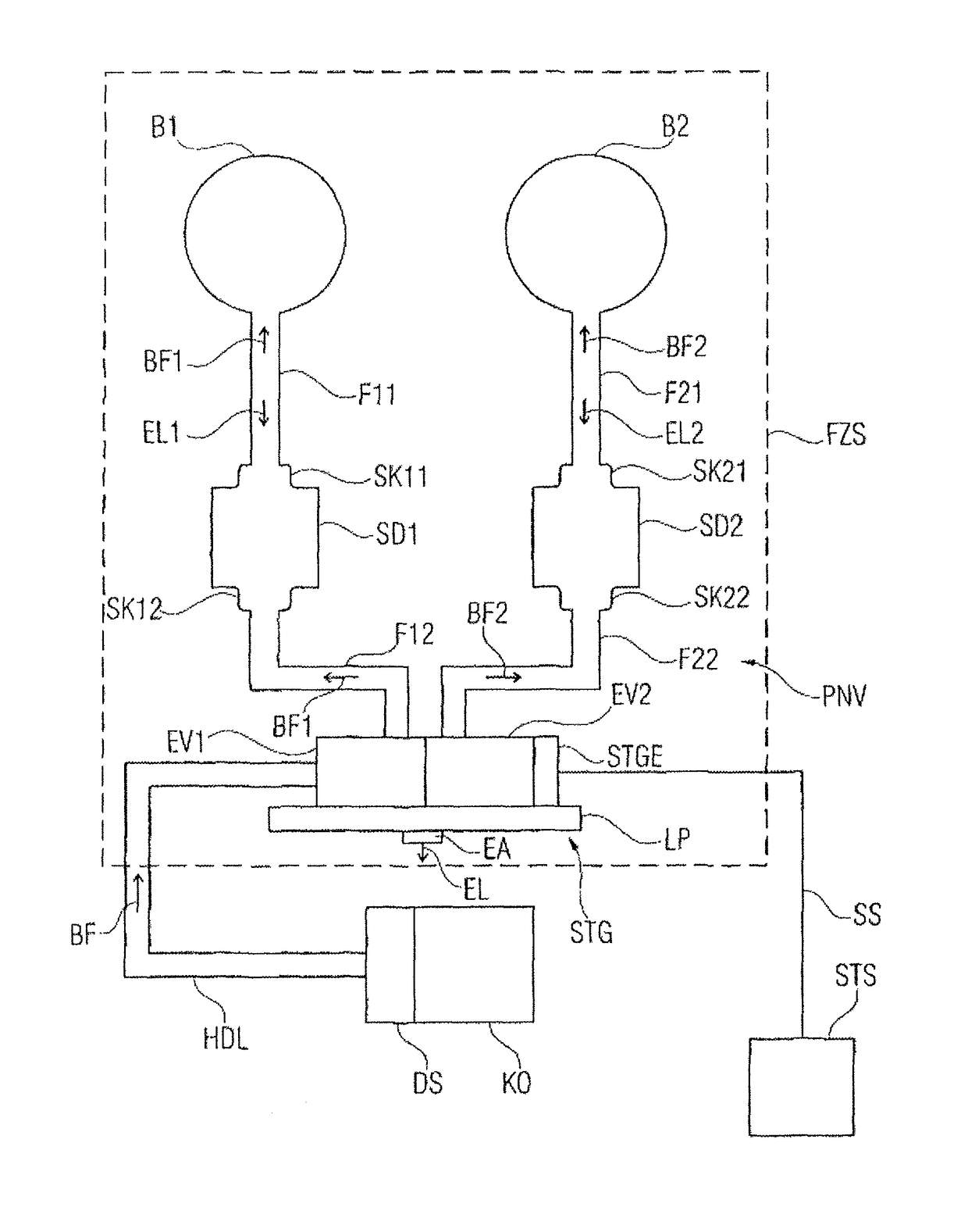
[0020]Reference will firstly be made to FIG. 1 which shows a schematic illustration of a vehicle seat FZS with a pneumatic adjustment arrangement PNV according to one embodiment of the invention. The vehicle seat FZS can have here a seat surface or a seat cushion and a backrest with which a user of the seat, such as, for example, the driver of a vehicle, comes into contact or against which he bears when he is located on the seat. In summary, the two surfaces against which a user of the seat bears can be referred to here as “seat bearing surfaces”.

[0021]In order to implement comfort functions in the vehicle seat FZS, according to the embodiment in FIG. 1, two chambers or bubbles B1 and B2 which can be filled with a pressure medium, in particular compressed air, are provided. Although only two bubbles are provided according to the embodiment illustrated in FIG. 1, it is also conceivable to provide only one or more than two bubbles, for example in order to implement comfort functions i...


PUM


Abstract

A pneumatic adjustment arrangement for a vehicle seat. The pneumatic adjustment arrangement has at least one chamber or bladder, which can be filled with a pressure medium, as an adjustment element. Furthermore, the pneumatic adjustment arrangement has a fluid line for the filling and / or evacuation of the chamber. Additionally, the pneumatic adjustment arrangement has a valve device which is provided in the fluid line for volume flow regulation. Finally, the pneumatic adjustment arrangement has a noise absorber which is likewise arranged in the fluid line in order to absorb noise generated in the fluid line. In this way, it is possible to create a pneumatic adjustment arrangement for a vehicle seat, in particular for comfort functions, such that objectionable noises during the execution of the comfort fiction are reduced.

Description

CROSS REFERENCE TO RELATED APPLICATIONS[0001]This application is the U.S. National Phase Application of PCT / EP2013 / 054400, filed Mar. 5, 2013, which claims priority to German Patent Application No. 10 2012 203 480.3, filed Mar. 6, 2012, the contents of such applications being incorporated by reference herein.FIELD OF THE INVENTION[0002]The present invention relates to a pneumatic adjustment arrangement for a vehicle seat having a sound absorber, and to a vehicle seat having a corresponding pneumatic adjustment arrangement for low-noise operation.BACKGROUND OF THE INVENTION[0003]In modern vehicle seats, bubbles or chambers which can be filled with compressed air are located in a region of the seat surface or seat backrest and can be supplied with compressed air via a respective compressed air line. By filling a respective bubble with compressed air, the volume thereof is increased so that as a result the properties of a seat backrest or seat surface in the contour can be changed. In ...

Claims


Application Information

Patent Timeline
Patent Type & Authority Patents(United States)
IPC IPC(8): A47C4/54B60N2/44B60N2/64B60N2/52B60N2/02B60N2/90
CPCB60N2/4415B60N2/0224B60N2/525B60N2/64Y10T137/6855B60N2/52B60N2/522B60N2/914B60N2/976
Inventor STEINBERGER, JOHANNWEICKMANN, STEFANZEHNDBAUER, MARCO
Owner CONTI TEMIC MICROELECTRONIC GMBH
Why Eureka
Try Eureka