Upper body motion measurement system and upper body motion measurement method

a motion measurement system and upper body technology, applied in the field of upper body motion measurement system and upper body motion measurement method, can solve the problems of inability to accurately assess the walking state of the person with high reliability, person discomfort or the feeling of an attached foreign object, etc., to prevent the occurrence of the difference in motion

Active Publication Date: 2017-10-31
HONDA MOTOR CO LTD +1
View PDF8 Cites 4 Cited by
  • Summary
  • Abstract
  • Description
  • Claims
  • Application Information

AI Technical Summary

Benefits of technology

[0022]Here, each of the inertia sensor units is provided with a set of the angular velocity sensor and the acceleration sensor. This makes it possible to estimate the attitude of each of the inertia sensor units based on a detection value of the angular velocity and a detection value of the acceleration indicated by the detection outputs of the angular velocity sensor and the acceleration sensor of the inertia sensor unit. As the arithmetic processing for the estimation, publicly known arithmetic processing, e.g. strap-down calculation, may be adopted.
[0088]According to the tenth aspect of the invention, therefore, a change in the posture of the upper body of a person (subject) can be properly measured.

Problems solved by technology

This tends to cause the person discomfort or the feeling of an attached foreign object.
Further, in some cases, the discomfort, the feeling of an attached foreign object or the weight of the fixing plate inconveniently causes the walking form of a person to be different from his / her normal walking form without the fixing plate attached.
This makes it impossible to properly assess the walking state of the person with high reliability.
This, however, would make it difficult to cause the attitude of the angular velocity sensor to accurately and stably follow the posture of the upper body of the person.
As a result, it becomes difficult to observe the posture change of the upper body of the person with high reliability.
Therefore, the measurement values of the angular velocity of the upper body are susceptible to the influence of noise components contained in the detection values of the angular velocity.
This is inconveniently prone to result in deteriorated measurement accuracy of the angular acceleration of the upper body.

Method used


Image

  • Upper body motion measurement system and upper body motion measurement method
  • Upper body motion measurement system and upper body motion measurement method
  • Upper body motion measurement system and upper body motion measurement method

Examples


first embodiment

[0100]The following will describe a first embodiment of the present invention with reference to FIG. 1 to FIG. 7.

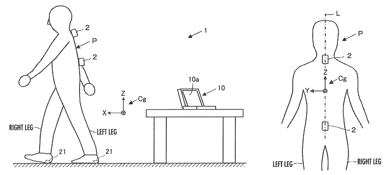
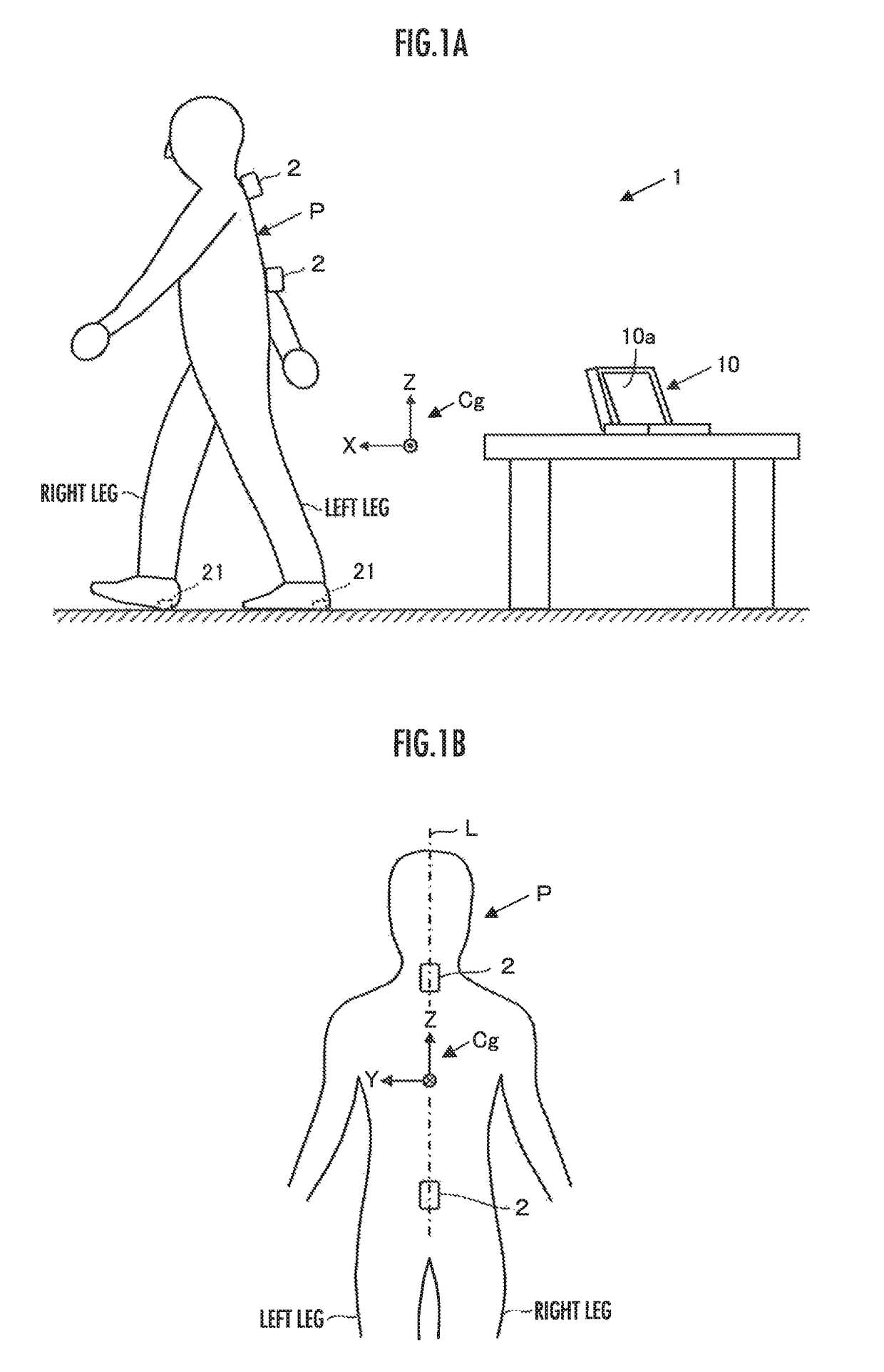
[0101]Referring to FIG. 1A and FIG. 1B, an upper body motion measurement system 1 according to the present embodiment has two inertia sensor units 2, 2 attached to a subject P, and a data acquisition device 10 that mainly acquires measurement data through communication with the inertia sensor units 2, 2.

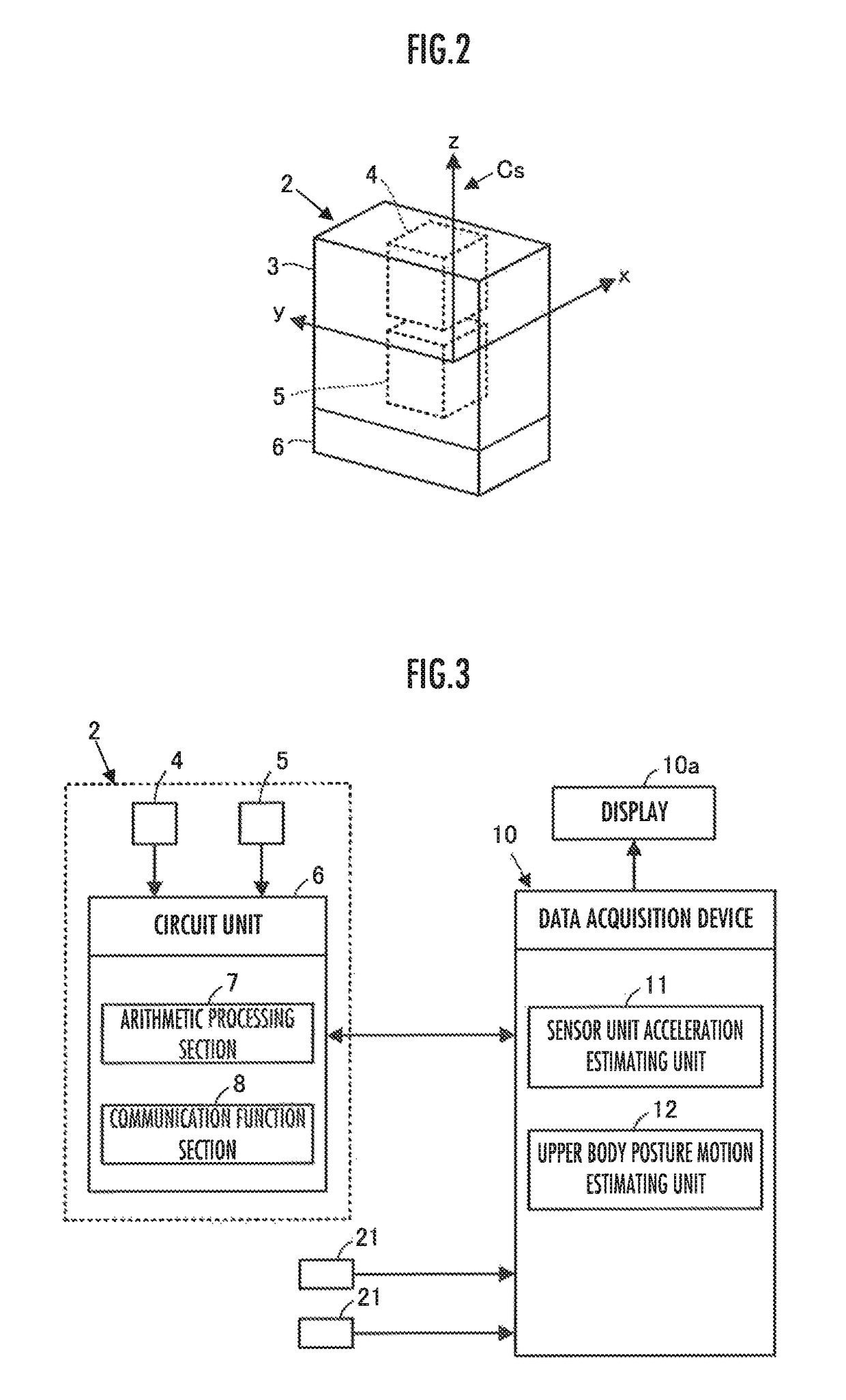
[0102]Each of the inertia sensor units 2 (hereinafter referred to simply as the sensor unit 2) includes an angular velocity sensor 4 and an acceleration sensor 5 housed in a chassis 3, and a circuit unit 6 having a communication function and the like, as illustrated in FIG. 2. The angular velocity sensor 4, the acceleration sensor 5 and the circuit unit 6 are fixed to the chassis 3.

[0103]The angular velocity sensor 4 is a sensor that detects a spatial (three-dimensional space) angular velocity vector. The angular velocity sensor 4 is constituted of a three-axis angular vel...

second embodiment

[0233]A second embodiment of the present invention will now be described with reference primarily to FIG. 8A and FIG. 8B. An upper body motion measurement system of the present embodiment differs from the upper body motion measurement system 1 of the first embodiment described above only in the layout of the sensor units and a part of the processing carried out by the data acquisition device. The description of the present embodiment, therefore, will be focused mainly on the aspects that are different from the first embodiment. Further, the description of the aspects that are the same as those of the first embodiment will be omitted.

[0234]Referring to FIG. 8A, a measurement system according to the present embodiment has four sensor units (inertial sensor units) 2, 2, 2, 2. The configuration of each of the sensor units 2 is the same as that in the first embodiment.

[0235]Of the four sensor units 2, 2, 2, 2, two sensor units 2, 2 are attached to a place in the vicinity of the base of t...


PUM


Abstract

An upper body motion measurement system1 has a plurality of inertia sensor units 2, each of which incorporating an angular velocity sensor 4 and an acceleration sensor 5. The plurality of the inertia sensor units 2 is attached to places that are different from each other on the upper body of a subject P. Based on the detection outputs of the angular velocity sensor 4 and the acceleration sensor 5, the attitude of each of the inertia sensor units 2 is estimated, and the acceleration thereof is further estimated. The angular acceleration of the upper body of the subject P is estimated based on the estimated accelerations of the plurality of the inertia sensor units 2.

Description

BACKGROUND OF THE INVENTION[0001]Field of the Invention[0002]The present invention relates to a system and a method for estimating the change in the posture of the upper body of a person (subject).[0003]Description of the Related Art[0004]Hitherto, in order to grasp the walking state of a person, the posture of a predetermined part of a walking person, or a change or the like of the posture has generally been measured using an angular velocity sensor, such as a gyro sensor.[0005]For example, Japanese Patent Application Laid-Open No. 2012-65723 (hereinafter referred to as Patent Document 1) describes a technique in which gyro sensors are attached to the waist and the thigh, the crus and the foot of each leg of a walker, and the joint angles of a hip joint, a knee joint, and an ankle joint are measured using the detection values of the gyro sensors.[0006]In the meantime, according to various experiments and studies carried out by the inventors of the present application, the change in...

Claims


Application Information

Patent Timeline
Patent Type & Authority Patents(United States)
IPC IPC(8): A61B5/00G01P15/18G01C21/16A61B5/107A61B5/11
CPCG01P15/18A61B5/1071G01C21/16A61B5/1121A61B5/1116A61B5/112
Inventor TAKENAKA, TORUIKEUCHI, YASUSHINAGATA, YOSUKEOHATA, KOJI
Owner HONDA MOTOR CO LTD
Why Eureka
Try Eureka