

Measurement circuit and measurement apparatus for wireless power transmission system
a technology of wireless power transmission system and measurement circuit, which is applied in the direction of electrical apparatus, transformer/inductance circuit, power supply testing, etc., can solve the problems of affecting the performance affecting the reliability of affecting the reliability of the system, so as to achieve the effect of reliable measurement of the characteristics of the power reception module, easy and precise inspection of the characteristics of the power transmission module and the power reception modul
- Summary
- Abstract
- Description
- Claims
- Application Information
AI Technical Summary
Benefits of technology
Problems solved by technology
Method used
Image

Examples
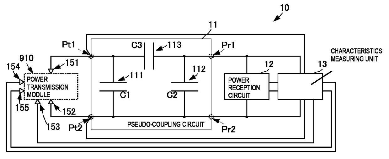
first embodiment
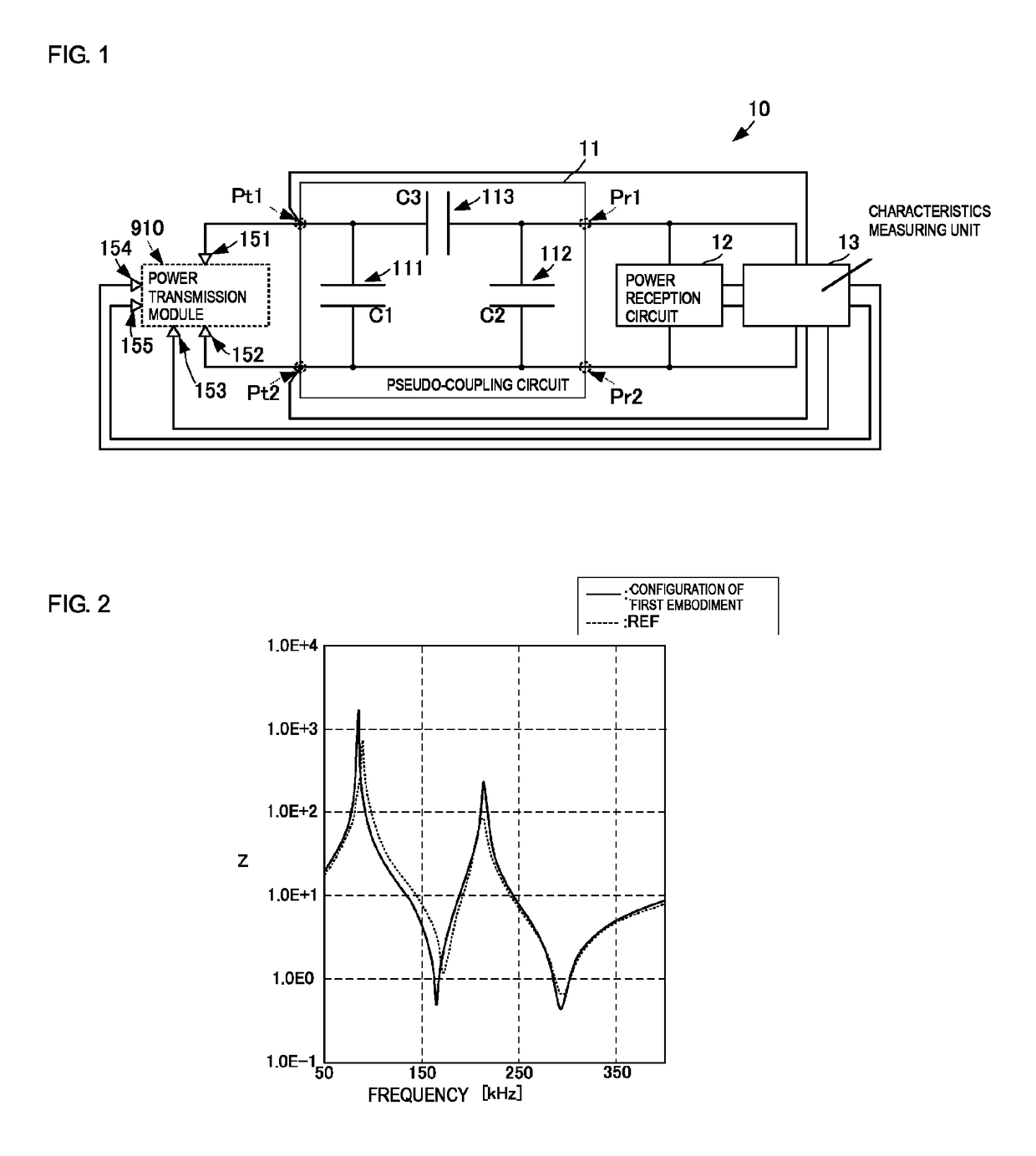
[0054]FIG. 2 is a graph illustrating impedance characteristics when the pseudo-coupling circuit 11 side (the first and second power-transmission-side terminals Pt1 and Pt2 side) is viewed from the power transmission module 910 in the measurement apparatus of the first embodiment and impedance characteristics when the power reception side is viewed from the power transmission module in the wirelessly connected real power transmission apparatus. Referring to FIG. 2, the horizontal axis represents frequency and the vertical axis represents impedance Z.
[0055]As illustrated in FIG. 2, appropriately setting the capacitances C1, C2, and C3 of the capacitors 111, 112, and 113, respectively, in the pseudo-coupling circuit 11 allows the impedance characteristics substantially coinciding with the impedance characteristics obtained when the wirelessly connected real power transmission apparatus is used to be realized.
[0056]As described above, the use of the configuration in the present embodime...
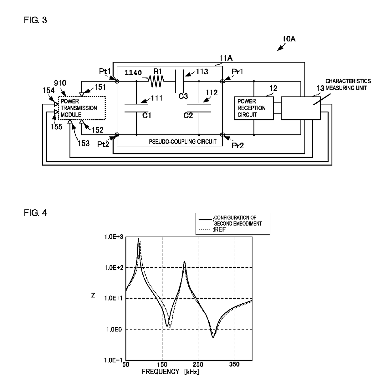
second embodiment
[0063]FIG. 4 is a graph illustrating impedance characteristics when the pseudo-coupling circuit 11A side (the first and second power-transmission-side terminals Pt1 and Pt2 side) is viewed from the primary side of a step-up transformer (not illustrated) in the power transmission module 910 in the measurement apparatus of the second embodiment and impedance characteristics when the power reception side is viewed from the power transmission module in the wirelessly connected real power transmission apparatus. Referring to FIG. 4, the horizontal axis represents frequency and the vertical axis represents the impedance Z.
[0064]As illustrated in FIG. 4, appropriately adjusting the capacitances C1, C2, and C3 of the capacitors 111, 112, and 113, respectively, in the pseudo-coupling circuit 11A and appropriately setting a resistance value R1 of the resistor 1140 allow the impedance characteristics more precisely coinciding with the impedance characteristics of the wirelessly connected real ...
fourth embodiment
[0084]The pseudo-coupling circuit 11D includes capacitors 115 and 116, in addition to the components in the pseudo-coupling circuit 11C illustrated in the The capacitors 115 and 116 correspond to “first and second additional capacitors” of the present invention.
[0085]The capacitor 115 is connected between the node between the first power-transmission-side terminal Pt1 and the capacitor 111 and the node between the second power-reception-side terminal Pr2 and the capacitor 112. The capacitor 116 is connected between the node between the second power-transmission-side terminal Pt2 and the capacitor 111 and the node between the first power-reception-side terminal Pr1 and the capacitor 112.
[0086]With the above configuration, the pseudo-coupling circuit 11D appropriately sets the capacitances C1 to C6 of the capacitors 111 to 116, respectively, to reproduce equivalent circuit constants of the coupling capacitance generator of the real apparatuses.
[0087]In addition, the use of the above ...
PUM
| Property | Measurement | Unit |
|---|---|---|
| power | aaaaa | aaaaa |
| electrical characteristics | aaaaa | aaaaa |
| voltage | aaaaa | aaaaa |
Abstract
Description
Claims
Application Information