Oligocyclic fatigue or oligocyclic and polycyclic fatigue test rig

a test rig and oligocyclic technology, applied in vibration testing, gas-turbine engine testing, instruments, etc., can solve the problems of affecting the service life of the blade-disc attachment, the difficulty of the model put in place lies in the input data required, and the test rig is not completely satisfactory in particular. , to achieve the effect of reducing the risk of misalignment of parts, limiting the risk of deformation of the support member, and limiting the risk of deformation

Active Publication Date: 2017-11-07
SAFRAN HELICOPTER ENGINES +1
View PDF9 Cites 2 Cited by
  • Summary
  • Abstract
  • Description
  • Claims
  • Application Information

AI Technical Summary

Benefits of technology

[0009]According to the invention, the element has a degree of freedom with respect to the support member, and the test piece has a degree of freedom with respect to the traction means. This double degree of freedom is particularly advantageous because the relative positions of the test piece and of the element supported by the support member can be adjusted precisely so as to ensure that the test piece does in fact bear against the or each bearing surface of the support member. Once the test piece and the element are correctly positioned, they are locked in these positions so that they maintain said positions at the start of the test. The invention thus ensures perfectly homogeneous contact at the start of the test.
[0014]Advantageously, the element is supported by a middle portion of the member which is connected by at least a first arm to a base which is fixed to the frame, said first arm being inclined in such a way that it is oriented substantially perpendicularly to a bearing surface of the element. Therefore, the first arm is substantially collinear with or tangential to the shearing forces applied to the bearing surface defined by the element. This makes it possible to limit the risks of deformation of the support member during a test.
[0015]The middle portion can be connected by at least a second arm to a cross bar which is substantially parallel to the base, said second arm being inclined in such a way that it is substantially parallel to a normal to the bearing surface defined by the element. The second arm is thus substantially parallel to the normal forces applied to the bearing surface of the element. This also makes it possible to limit the risks of deformation of the support member during a test, and considerably reduces the risk of misalignment of the contact of the parts. The invention thus makes it possible to maintain the contact of the parts for the entire duration of the test.
[0016]The support member can comprise two elements which are mounted so as to rotate on two middle portions of the member, respectively, and about first axes which are parallel to and at a distance from one another, said elements comprising bearing surfaces which are intended to reproduce portions of two adjacent blade roots of a rotor wheel. In other words, the test rig makes it possible to reproduce two blade-disc contacts.
[0019]This position of the bearing region makes it possible to ensure maximum sliding of the parts in the region of the contact whilst limiting the movements of the assembly. This makes it possible to equip the test rig with a plurality of instruments and in particular with a camera for viewing the bearing region.

Problems solved by technology

Said loads affect the service life of the blade-disc attachments.
The difficulty of the model put in place lies in the input data required.
However, said test rigs are not completely satisfactory in particular because the homogeneity of the contact between the parts is not guaranteed at the start of the test and for the entire duration of the test, and this can distort the calculations for assessing the service life.
In addition, the support member and the test piece are relatively bulky in said test rigs.
Furthermore, it can be difficult to equip said test rigs with measuring and control instruments, and to have easy access to said instruments.
Lastly, said test rigs do not always permit very representative assessments with respect to the industrial application of the parts.

Method used


Image

  • Oligocyclic fatigue or oligocyclic and polycyclic fatigue test rig
  • Oligocyclic fatigue or oligocyclic and polycyclic fatigue test rig
  • Oligocyclic fatigue or oligocyclic and polycyclic fatigue test rig

Examples


Embodiment Construction

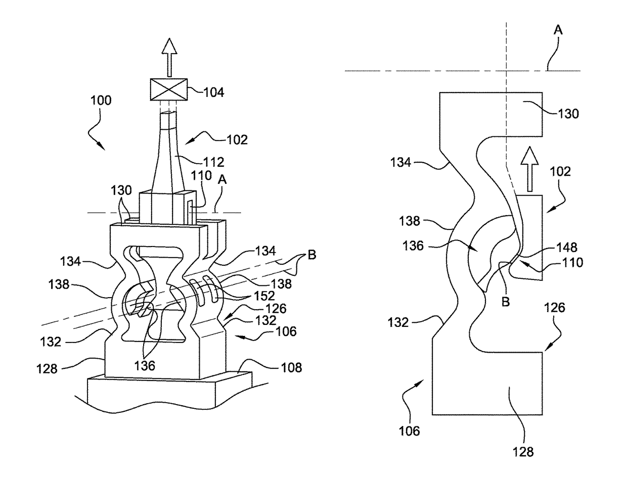
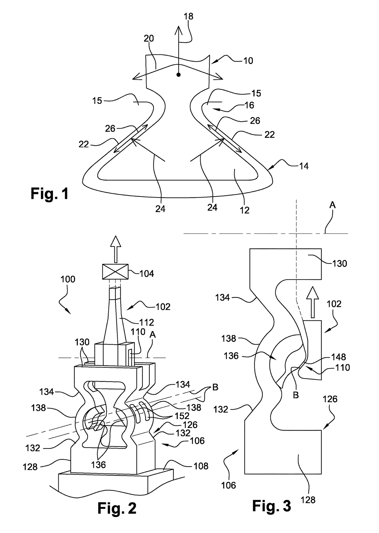
[0030]Reference is firstly made to FIG. 1, which schematically shows a blade-disc attachment of a turbine engine, the blade 10 comprising a root 12 which is inserted in a recess 14 in the periphery of a rotor disc 16, said disc comprising an annular array of recesses 14 of this type for receiving blade roots. The assembly formed by the disc 16 and the blades 10 form a rotor wheel of the turbine engine. In this case, the root 12 is of the dovetail type. Two adjacent recesses 14 in the disc 16 are separated from one another by a tooth 15, the teeth 15 located on either side of the root 12 of the blade from FIG. 1 being shown in part.

[0031]During operation, the blade 10 is subjected to centrifugal forces (arrow 18) and the vane thereof has a tendency to oscillate (arrow 20), causing the lateral portions of the blade root 12 to bear and slide against lateral contact surfaces of the recess 14 in the disc. The arrows 24 show normal forces which are applied to the surfaces facing the blade...


PUM

PropertyMeasurementUnit
distanceaaaaaaaaaa
flexibleaaaaaaaaaa
centrifugal forcesaaaaaaaaaa

Abstract

A low-cycle fatigue test rig reproduces bearing of turbine engine parts. The test rig includes a support member that is fixed to a frame and defines at least one bearing surface. A test piece is connected to a traction element for loading the test piece so that the test piece bears against the at least one bearing surface of the support member. The at least one bearing surface is supported by a support element that is mounted to rotate about a first axis on the support member. The test piece is connected to the traction element for articulation around a second axis that is perpendicular to the first axis. The test rig is configured to enable adjusting and locking the support element and the test piece in positions around the above-mentioned axes.

Description

TECHNICAL FIELD[0001]The present invention relates to a low-cycle, and optionally combined low-cycle and high-cycle, fatigue test rig, for reproducing bearing of turbine engine parts, such as at least one blade root bearing against a recess contact surface of a rotor disc.PRIOR ART[0002]A turbine engine rotor disc comprises, on the periphery thereof, an annular array of recesses into which blade roots are fitted, which are for example of the dovetail type, to form a rotor wheel. During operation, the blades are subjected to centrifugal forces, and the roots thereof bear against lateral contact surfaces of the recesses in the disc. The blades are further subjected to oscillations related to the aerodynamic forces which cause relative sliding between the blade roots and the disc. Said loads affect the service life of the blade-disc attachments.[0003]The analysis of the service life of the blade-disc attachments is based on calculations which are made complex by the effect of contact o...

Claims


Application Information

Patent Timeline
Patent Type & Authority Patents(United States)
IPC IPC(8): G01N3/00G01N3/32G01M7/02G01M15/14G01N3/02G01N3/04
CPCG01N3/32G01N3/04G01N3/02G01M7/027G01M15/14G01N2203/0005G01N2203/0008G01N2203/0423
Inventor MERIAUX, JEAN VINCENT MANUELPUECH, GUILLAUMERUIZ-SABARIEGO, JUAN-ANTONIOSERRES, NATHALIEHOUZE, LAURENT
Owner SAFRAN HELICOPTER ENGINES
Why Eureka
Try Eureka