Electrical switching device and associated electrical traction box

a technology of switching device and electrical traction box, which is applied in the direction of locomotives, casings/cabinets/drawers, casings/cabinets/drawers details of electric apparatus, etc., can solve the problems of complex structure of switching device and the inability to improve the heat exchange performance of cooling device, so as to achieve improved heat exchange performance and simplified structure

Active Publication Date: 2020-05-05
ALSTOM TRANSPORT TECH SAS
View PDF18 Cites 1 Cited by
  • Summary
  • Abstract
  • Description
  • Claims
  • Application Information

AI Technical Summary

Benefits of technology

[0007]The present invention therefore aims to propose a switching device for an electrical power module able to be integrated into an electrical traction box having a simplified structure and providing improved heat exchange performance with an associated cooling device.
[0009]With the switching device according to the invention, the switching device has a simplified structure, since the switching element does not need to be configured to withstand the bearing force directly and any risk of deformation of the switching element is avoided. Furthermore, the pressing elements used are less complex, and in particular have dimensions making them easier to assemble, since they extend between the support element and the base.
[0010]Furthermore, the thermal performance of the switching device according to the invention is improved, since the fact that the pressing elements exert the bearing force on the base makes it possible to improve the quality of the contact between the cooling device and the base, and therefore the heat exchanges between the switching element and the cooling device.
[0013]the fastening system is able to fasten the switching device removably to the cooling device;

Problems solved by technology

However, in such a power module, the structure of the switching device remains complex and the performance of the heat exchanges with the cooling device remains to be improved.

Method used


Image

  • Electrical switching device and associated electrical traction box
  • Electrical switching device and associated electrical traction box
  • Electrical switching device and associated electrical traction box

Examples


Embodiment Construction

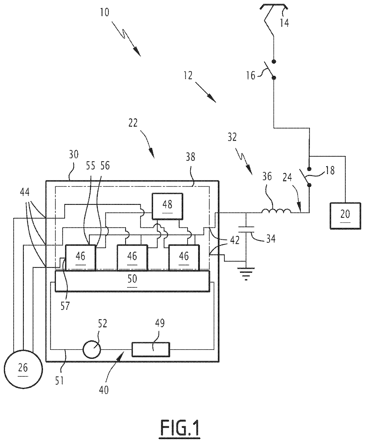
[0028]In FIG. 1, an electric transport vehicle 10, such as a railway vehicle, is shown schematically.

[0029]The vehicle 10 comprises a traction chain 12.

[0030]The traction chain 12 includes a pantograph 14 able to be connected to a catenary, not shown, an electrical circuit breaker 16 connected to the pantograph 14 and an electrical switch 18 connected to the electrical circuit breaker 16.

[0031]The traction chain 12 also comprises a traction assembly 22 connected to the electoral switch 18, for example via which a DC bus 24.

[0032]As an optional addition, the traction chain 12 comprises an auxiliary piece of equipment 20 connected between the electrical circuit breaker 16 and the electrical switch 18, bypassing the electrical switch 18.

[0033]The electrical circuit breaker 16, the electrical switch 18 and the auxiliary piece of equipment 20 are known in themselves, and are not described in more detail. The auxiliary piece of equipment 20 is for example a static converter.

[0034]The trac...


PUM


Abstract

This electrical switching device, able to be integrated into an electrical traction box including a cooling device of the switching device, includes an electrical assembly provided with an electrical switching element. This switching device also includes a base for receiving the electrical assembly, intended to be positioned between the electrical assembly and the cooling device, and pressing elements for pressing the electrical assembly extending between the support element and the base and configured to exert a bearing force on the base, able to keep the base bearing against the cooling device when the switching device is integrated into the traction box.

Description

[0001]This patent application claims the benefits of document FR 17 56422 filed on Jul. 7, 2017 which is hereby incorporated by reference.FIELD OF THE INVENTION[0002]The present invention relates to an electrical switching device for an electrical power module able to be integrated into an electrical traction box of a transport vehicle and an associated traction box comprising an electrical power module provided with the switching device and a cooling device able to cool the switching device.[0003]The switching device comprises an electrical assembly provided with an electrical switching element, and a system for pressing the electrical assembly comprising a support element of the electrical assembly and pressing elements for the electrical assembly.[0004]The invention applies to the transportation field, in particular rail transport, in particular to railway transport, particularly to electric traction transport vehicles, such as locomotives and electric railcars.BACKGROUND OF THE ...

Claims


Application Information

Patent Timeline
Patent Type & Authority Patents(United States)
IPC IPC(8): H05K7/20H05K5/00H02M7/00B61C3/00H05K5/02
CPCB61C3/00H05K5/0217H05K7/209H05K7/2049H05K5/0204H02M7/003H05K5/0008H05K7/20927
Inventor VALLE, GILLESNICOLAU, SÉBASTIEN
Owner ALSTOM TRANSPORT TECH SAS
Why Eureka
Try Eureka