System and method for synchronization among multiple PLL-based clock signals

a clock signal and synchronization technology, applied in the direction of generating/distributing signals, pulse automatic control, electrical equipment, etc., can solve the problems of adding timing uncertainty, overall noise and clock uncertainty, and achieve the effect of reducing clock jitter and timing uncertainty, reducing signal propagation loss, and facilitating signal distribution

Active Publication Date: 2017-11-07
ANALOG DEVICES INT UNLTD
View PDF4 Cites 0 Cited by
  • Summary
  • Abstract
  • Description
  • Claims
  • Application Information

AI Technical Summary

Benefits of technology

[0015]A clock signal of the present invention has reduced clock jitter and timing uncertainty, as compared to a series-connected clock synchronization system, as there is only a single frequency divider between the frequency reference signal and any output clock signal. As the output signals of a PLL typically have frequencies that are significantly higher than the frequency of the input frequency reference signal, the number of high-frequency interconnections required under the present invention among frequency dividers is reduced, thus providing a significant advantage in reduced signal propagation loss and easier signal distribution.

Problems solved by technology

Each cascaded divider adds timing uncertainty as a result of variations of clock propagation delay, and as a result of noise in the form of clock jitter.
The resulting overall noise and clock uncertainty depend upon the number of dividers present between the reference signal and the output clock signal in question.

Method used


Image

  • System and method for synchronization among multiple PLL-based clock signals
  • System and method for synchronization among multiple PLL-based clock signals
  • System and method for synchronization among multiple PLL-based clock signals

Examples


Embodiment Construction

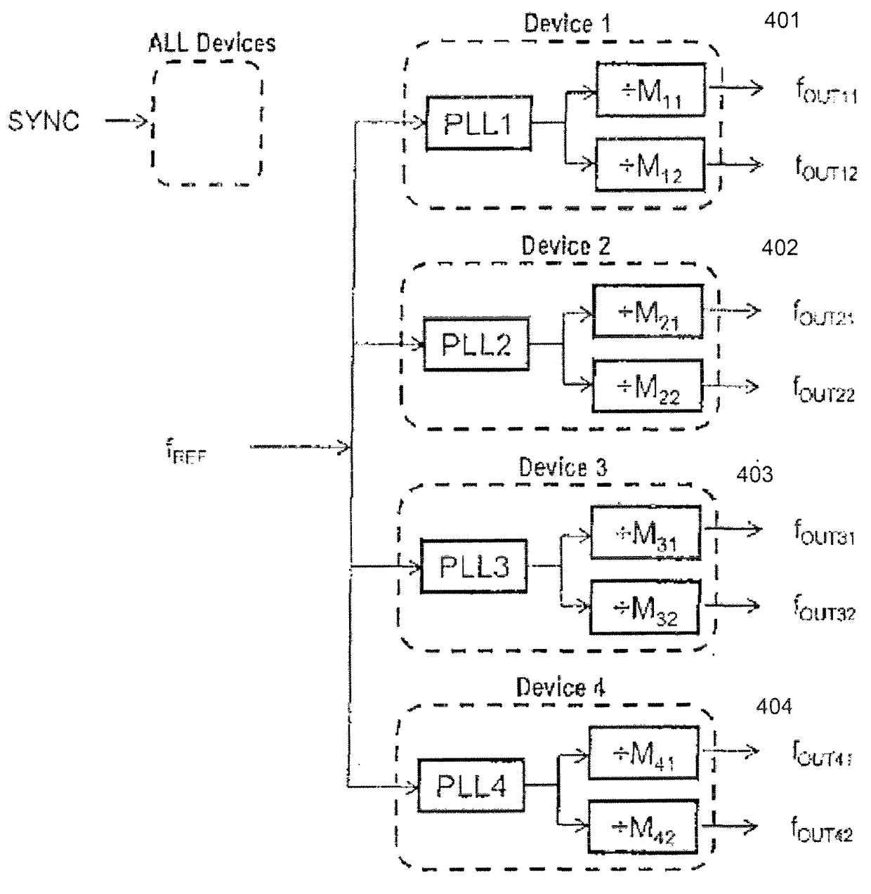
[0023]FIG. 4 shows system 400, which uses PLLs connected in parallel, according to one embodiment of the present invention. As shown in FIG. 4, a number of clock generators 401-404 receive frequency reference signal fREF. Each of clock generators 401-404 includes a PLL (e.g., PLL1, PLL2, PLL3 or PLL4), which provides an output signal to multiple output frequency dividers (e.g., one or more output frequency dividers M11, M12, M21, M22, M31, M32, M41, or M42) to provide output signals of various frequencies (e.g., output signals fOUT11, fOUT12, fOUT21, fOUT22, fOUT31, fOUT32, fOUT41 and fOUT42). Synchronization signal SYNC is provided to all clock generators. In FIG. 4, PLL1, PLL2, PLL3 and PLL4 each include a reference signal frequency divider (i.e., an R-divider).

[0024]As described above, to align the output signals of PLLs, the signals of their respective reference signal R-dividers must be aligned. When an output signal of a PLL drives an output frequency divider to provide an out...


PUM


Abstract

A method synchronizes clock signals generated by a system that includes multiple PLLs that are connected in parallel and output frequency dividers driven by the PLLs. The system receives a common frequency reference signal and a common synchronization signal. Each PLL may have a reference signal frequency divider. The reference frequency divider may be phase-reset, for example, by a transition to a first logic state in the synchronization signal, and the output frequency dividers are each phase-reset, for example, by a transition to a second logic state following the transition to the first logic state in the synchronization signal. The transition to the first logic state may be, for example, a rising edge.

Description

CROSS REFERENCE TO RELATED APPLICATIONS[0001]The present application relates to and claims priority of U.S. provisional patent application, Ser. No. 62 / 254,037, filed Nov. 11, 2015, entitled “System and Method for Synchronization Among Multiple PLL-based Clock Signals.” The disclosure of the Application is hereby incorporated by reference in its entirety.BACKGROUND OF THE INVENTION[0002]1. Field of the Invention[0003]The present invention relates to aligning or synchronizing multiple clock synthesizers or phase-locked loops (PLLs) that operate in parallel.[0004]2. Discussion of the Related Art[0005]Synchronization of timing signals is required, for instance, when aligning data sampling events in analog-to-digital converters that are driven by clock signals. Similarly, synchronization of timing signals is required to phase-align different carrier radio waves to achieve constructive interference. There are many systems that require—either because the number of clock signals they used ...

Claims


Application Information

Patent Timeline
Patent Type & Authority Patents(United States)
IPC IPC(8): G06F1/12H03L7/23G06F1/10
CPCG06F1/12H03L7/23G06F1/10
Inventor EZELL, RICHARD WILLIAMMUMPER, ERIC WRIGHT
Owner ANALOG DEVICES INT UNLTD
Why Eureka
Try Eureka