
Method and system for reducing the effect of component recovery

a component and recovery technology, applied in the field of component recovery, can solve the problems of aging of transistors, imbalance in static probability of one logical state versus another, degradation or end-of-life effects of transistors, etc., and achieve the effects of reducing the aging of components, reducing the effect of aging, and reducing the effect of component recovery

Active Publication Date: 2015-06-02
ALTERA CORP
View PDF2 Cites 1 Cited by
  • Summary
  • Abstract
  • Description
  • Claims
  • Application Information

AI Technical Summary

Benefits of technology

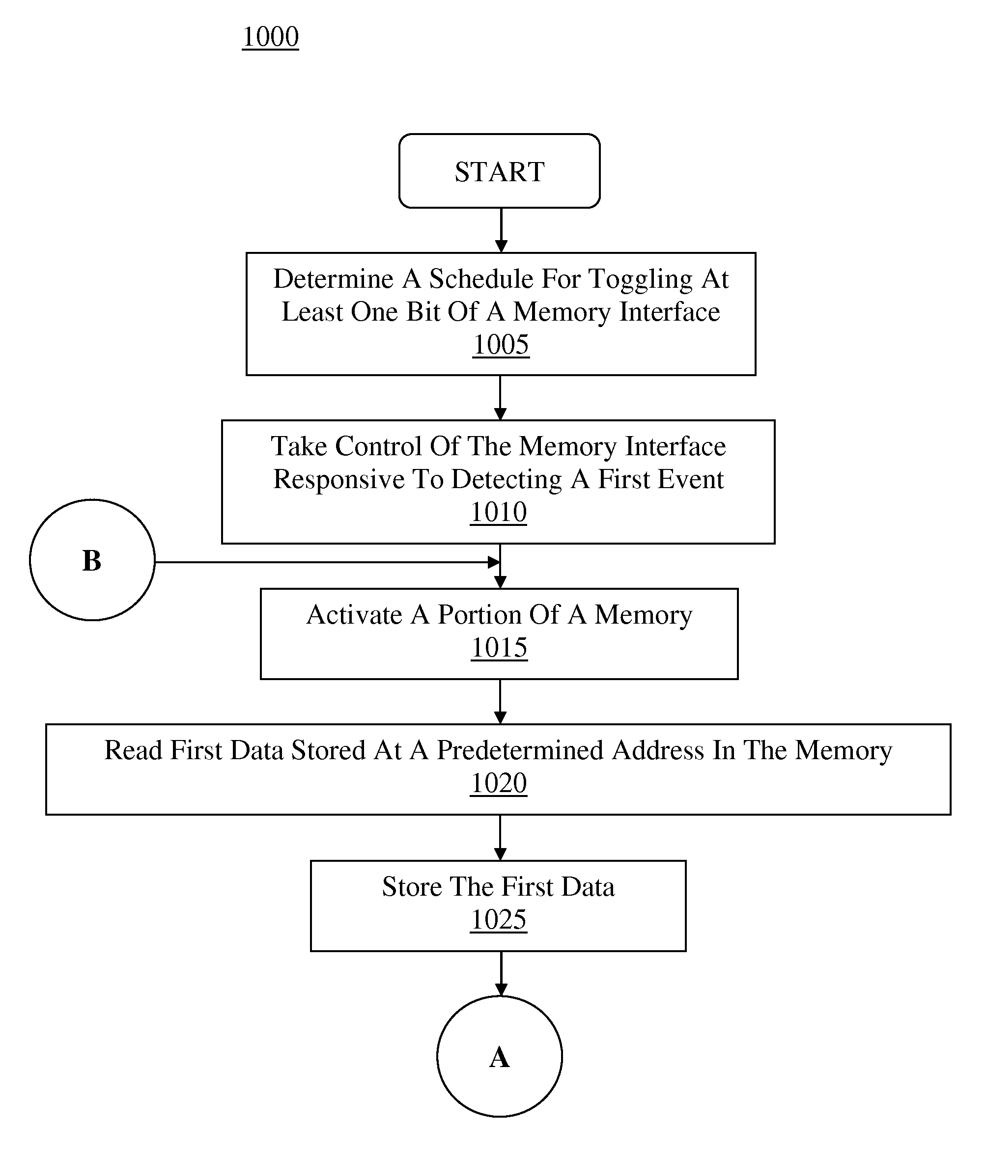
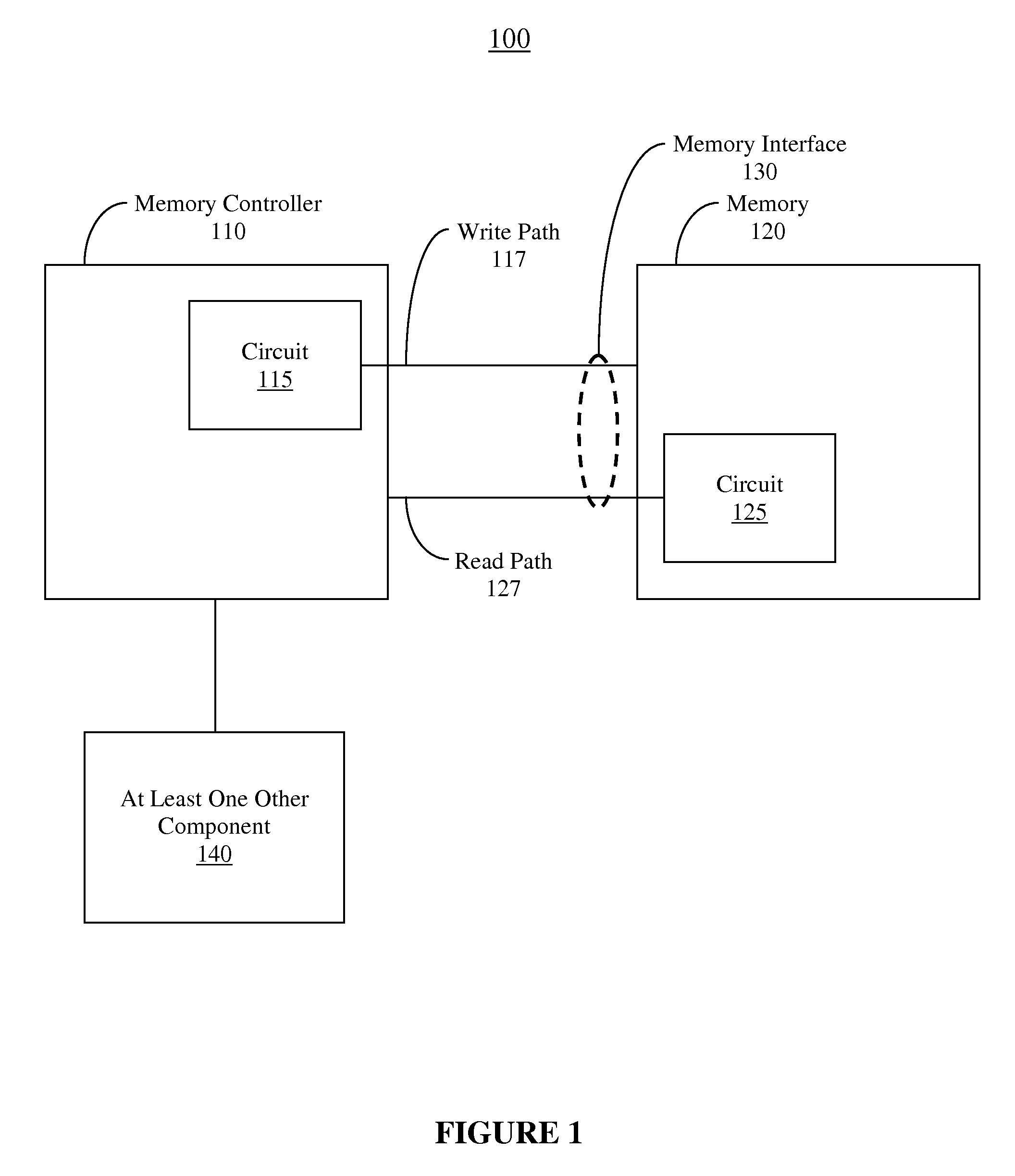
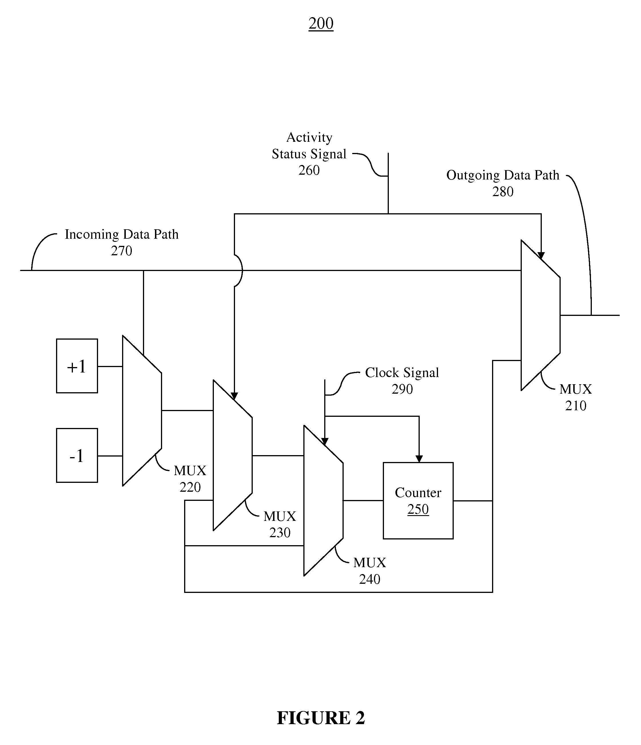
The present invention provides methods, computer-readable media, and systems for reducing the aging of components in data paths and the effects of recovery of aged components. This is achieved by periodically communicating data over a data path that includes at least one bit that is toggleled during refresh intervals. This helps to reset the recovery period for any transistors in the data path associated with the bit, reducing timing uncertainty and allowing for faster data transmission. By limiting the amount of recovery experienced by the transistor, recovery of transistors in the data path may be limited to a predetermined amount, resulting in a smaller system margin and higher data transmission speeds.

Problems solved by technology

Transistors in a data path or interface can experience degradation or end-of-life (EOL) effects if stressed or used in certain ways.
For example, aging of the transistors can occur if data signals are communicated which result in an imbalance in the static probability of one logical state versus another.
Aging of transistors can increase delay or uncertainty associated with transitions between logical states.
As such, timing uncertainty caused by variation in the total delay can significantly decrease system margin, thereby limiting the speed of data transmission over conventional interfaces using conventional communication circuitry.
Accordingly, the delay variation from the recovery effect can further decrease the system margin, thereby further limiting the speed of data transmission over conventional interfaces using conventional communication circuitry.

Method used


Image

  • Method and system for reducing the effect of component recovery
  • Method and system for reducing the effect of component recovery
  • Method and system for reducing the effect of component recovery

Examples


Embodiment Construction

[0023]Reference will now be made in detail to embodiments of the present invention, examples of which are illustrated in the accompanying drawings. While the present invention will be discussed in conjunction with the following embodiments, it will be understood that they are not intended to limit the present invention to these embodiments alone. On the contrary, the present invention is intended to cover alternatives, modifications, and equivalents which may be included with the spirit and scope of the present invention as defined by the appended claims. Furthermore, in the following detailed description of the present invention, numerous specific details are set forth in order to provide a thorough understanding of the present invention. However, embodiments of the present invention may be practiced without these specific details. In other instances, well-known methods, procedures, components, and circuits have not been described in detail so as not to unnecessarily obscure aspect...


PUM


Abstract

Methods, computer-readable mediums and systems for reducing transistor recovery are disclosed. Data which toggles at least one bit may be periodically communicated over a data path, where toggling of at least one bit may effectively reset the recovery period for any transistors in the data path associated with the at least one bit. Timing uncertainty associated with a given transistor may be reduced by limiting the amount of recovery experienced by the transistor. Accordingly, recovery of transistors in a data path may be limited to predetermined amount by toggling bits of the data path at a predetermined frequency, thereby reducing timing uncertainty and allowing a smaller system margin and / or higher data transmission speeds.

Description

BACKGROUND OF THE INVENTION[0001]Transistors in a data path or interface can experience degradation or end-of-life (EOL) effects if stressed or used in certain ways. For example, aging of the transistors can occur if data signals are communicated which result in an imbalance in the static probability of one logical state versus another. Static probability of a particular logical state can be expressed as a ratio of the time spent in the particular logical state to the time spent in all logical states.[0002]Aging of transistors can increase delay or uncertainty associated with transitions between logical states. Since each aged transistor can contribute a respective delay, the total delay experienced by a signal communicated over a data path is typically increased by the number of transistors in the data path. As such, timing uncertainty caused by variation in the total delay can significantly decrease system margin, thereby limiting the speed of data transmission over conventional i...

Claims


Application Information

Patent Timeline
Patent Type & Authority Patents(United States)
IPC IPC(8): H03M13/00G06F11/10H03M13/33H04L12/70
CPCG06F11/108H03M13/336H04L2012/5674G06F11/3027G06F11/3058G06F11/3093H03K17/56G06F2201/88H03K19/01728G11C7/1006
Inventor CHIU, GORDONAZIZI, NAVID
Owner ALTERA CORP
Learn More