Commissioning system for a lighting system

a lighting system and commissioning system technology, applied in the direction of electroluminescent light sources, electric lighting sources, close-range type systems, etc., can solve the problems of cumbersome process, high cost and error rate, and difficulty in identifying the exact physical location of a specific luminaire in a long row, so as to facilitate the detection of the second visual pattern, the effect of easy identification

Inactive Publication Date: 2017-11-14
SIGNIFY HLDG BV
View PDF15 Cites 0 Cited by
  • Summary
  • Abstract
  • Description
  • Claims
  • Application Information

AI Technical Summary

Benefits of technology

[0010]This system enables individual lighting units to be identified by requiring only their relative position within a set to be visually identified. The set may be a small number of lighting units compared to the overall lighting system, for example a set of 8 luminaires. By using the relative position within a set as the visual input, a reliable visual commissioning system can be created. The invention may make use of the physical wiring constraints (of controllers being associated with spatially grouped lighting units), so that visual identification can be based on relatively small lighting area.
[0013]The control output signal, to display the light output pattern for the set or further set of lighting units, may be a low light intensity static pattern control output signal. In such a system the low light intensity static pattern can be identified easily without dazzling the observer or monitor and allow easier detection of the second visual pattern.
[0014]The further control output signal, to change the light output pattern at the lighting unit to enable the lighting unit within the set or further set to be visually identified, may be a dynamic lighting pattern control output signal. In such a system the dynamic pattern, for example a blinking, can be easily identified and enable the observer or monitor to determine the relative location of the lighting unit within the first visual pattern actuated luminaires.
[0019]According to a second aspect there is provided a commissioning method for a lighting system comprising a plurality of controllers, each controller controls a set of lighting units spatially clustered as a group and controlled using a set of control outputs, wherein each control output is for controlling one or more lighting units of the set, the method being for mapping each lighting unit of the set to a respective logical address in dependence on the physical position of the lighting unit, the method comprising: selecting one of the sets of lighting units connected to a controller, and identifying the lighting units within the set by means of discovering unique identifiers associated with the drivers and / or lamps within each of said lighting units; controlling the identified lighting units to display a light output pattern; for a lighting unit within the set: changing the light output pattern to enable a position of that lighting unit within the set to be visually identified; and receiving a position of the visually identified lighting unit within the set as an input; and based on the position of the visually identified lighting unit within the set, assigning a logical address to the visually identified lighting unit within the set. This method enables individual lighting units to be identified by requiring only their relative position within a set to be visually identified. The set may be a small number of lighting units compared to the overall lighting system, for example a set of 8 luminaires. By using the relative position within a set as the visual input, a reliable visual commissioning system can be created. The invention makes use of the physical wiring constraints (of controllers being associated with spatially grouped lighting units), so that visual identification can be based on relatively small lighting area.
[0034]Receiving the position of the visually identified lighting unit within the set as an input may cause the commissioning system to: receive an image captured by a camera; and process the image to determine the position of the visually identified lighting unit within the set.

Problems solved by technology

This process is cumbersome, expensive and error-prone.
Experiences with this method from other application areas (e.g. street lighting) indicate that the multitude of process steps (label generation, label application in factory, label scanning, assignment to controller output ID) causes up to 60% error rate in practical circumstances.
Existing methods have the problem that it is very difficult to identify the exact physical location of a specific luminaire in a long row, even when only a single luminaire is lit.
For example it may be too difficult to count the luminaire number from a specific location within a circle of 300 luminaires.

Method used


Image

  • Commissioning system for a lighting system
  • Commissioning system for a lighting system
  • Commissioning system for a lighting system

Examples


Embodiment Construction

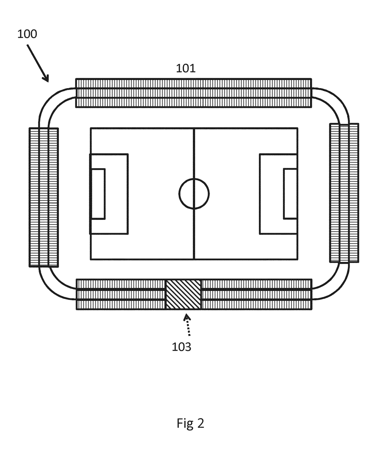
[0044]The concepts as described herein show a commissioning system for a lighting system to enable an efficient determination of logical addresses to lighting units or luminaires within a complex lighting system. Although the following examples have been described with respect to stadium or arenas such as football stadium, it is understood that the commissioning system and methods described herein could be applied to various large scale lighting applications such as lighting for swimming pool arenas and velodromes.

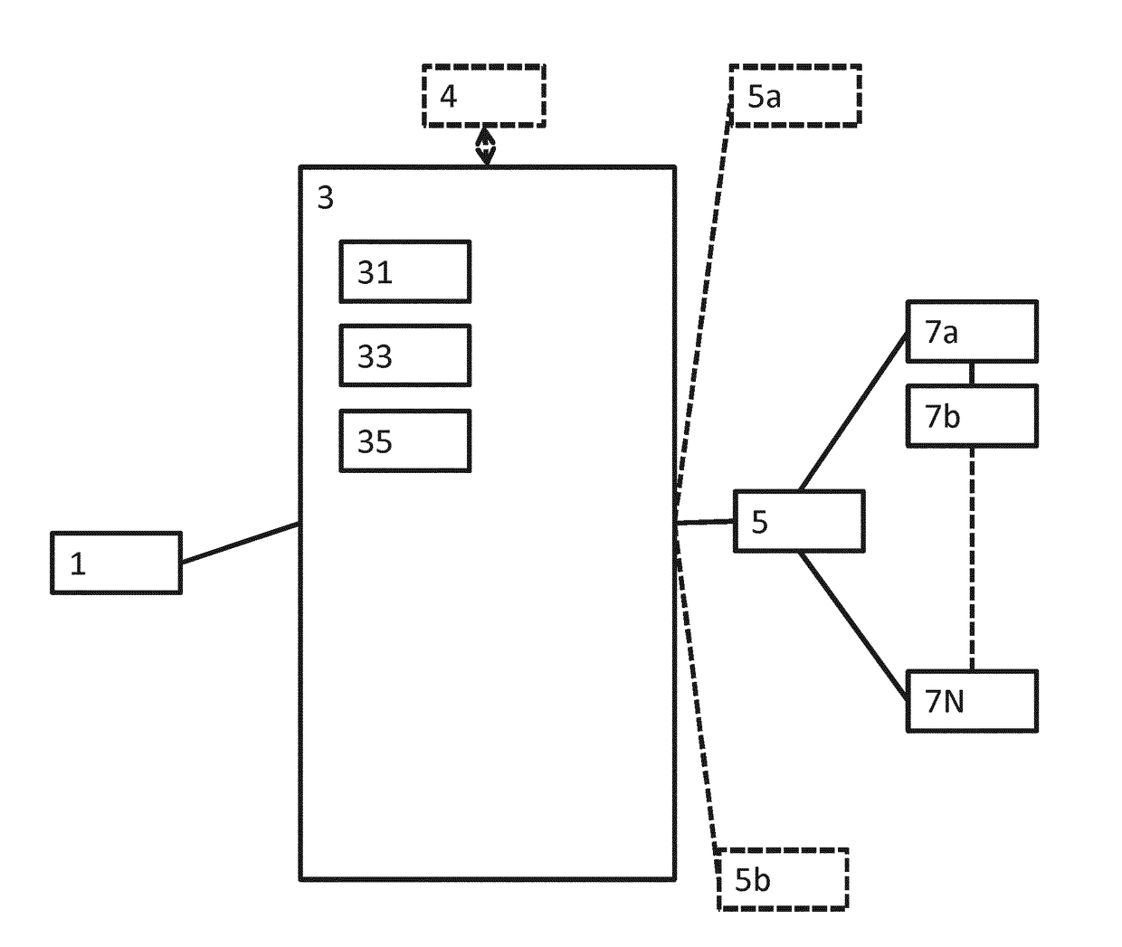
[0045]With respect to FIG. 1 an example lighting system is shown incorporating a commissioning system for a lighting system according to some embodiments.

[0046]The lighting system may comprise lighting controllers 5, shown in FIG. 1 as three lighting controllers 5, 5a, 5b. The lighting controllers 5, 5a, 5b are each configured to control a clustered group (or set) of lighting units 7a, . . . 7N. It is understood that the controllers 5, 5a, 5b can be any suitable lighting c...


PUM


Abstract

A commissioning system (3) for a lighting system, the lighting system comprising a plurality of controllers (5), each controller (5) adapted to control a set of lighting units (7) spatially clustered as a group and controlled using a set of control outputs, wherein each control output is for controlling one or more lighting units of the set, the commissioning system comprising: an identification unit (31) for identifying the set of lighting units connected to a controller (5) from the plurality of controllers; a commissioning controller (33) for controlling the identified set of lighting units via the controller (5), wherein the commissioning controller is adapted to enable the controller (5) to: generate a control output signal for the set of lighting units to display a light output pattern; and for a lighting unit within the set, to generate a further control output signal, to change the light output pattern at the lighting unit to enable the lighting unit within the set to be visually identified; a commissioning unit (35) adapted to: receive as an input a position of the visually identified lighting unit within the set; and based on the position of the visually identified lighting unit within the set to assign a logical address to the visually identified lighting unit within the set.

Description

CROSS-REFERENCE TO PRIOR APPLICATIONS[0001]This application is the U.S. National Phase application under 35 U.S.C. §371 of International Application No. PCT / EP2015 / 066932, filed on Jul. 23, 2015, which claims the benefit of European Patent Application No. 14180933.5, filed on Aug. 14, 2014. These applications are hereby incorporated by reference herein.FIELD OF THE INVENTION[0002]This invention is generally related to a commissioning system for a lighting system, and in particular a commissioning system for an arena or stadium lighting system.BACKGROUND OF THE INVENTION[0003]In high-end arena (field, pitch or stadium) lighting, like the Philips ArenaVision products, a large number of lighting units or luminaires are distributed around an arena or stadium to attempt to create a uniform light intensity on the field or pitch. For example a football stadium may have a lighting plan or design where the lighting system contains more than 100 luminaires, and typically 200 to 600 luminaires...

Claims


Application Information

Patent Timeline
Patent Type & Authority Patents(United States)
IPC IPC(8): H05B37/02H05B33/08H04B10/116H04B10/27H05B44/00
CPCH05B37/0272H05B33/0854H04B10/27H04B10/116H05B47/175H05B45/10H05B47/18
Inventor VAN DER BRUG, WILLEM PETER
Owner SIGNIFY HLDG BV
Why Eureka
Try Eureka