A non-contact electromagnetic pinch valve

A non-contact, electromagnetic clamp technology, used in diaphragm valves, valve devices, valve details, etc., can solve the problem of difficult to adapt to high-viscosity fluid viscous fluid over-current control, etc., to achieve simple structure, low use requirements, and reduced The effect of the work schedule

Inactive Publication Date: 2019-10-25
XIAN UNIV OF TECH
View PDF7 Cites 0 Cited by
  • Summary
  • Abstract
  • Description
  • Claims
  • Application Information

AI Technical Summary

Problems solved by technology

[0003] The purpose of the present invention is to provide a non-contact electromagnetic pinch valve to solve the problem that the existing electromagnetic valve is difficult to adapt to the flow control of high-viscosity fluid and viscous fluid containing particles

Method used


Image

  • A non-contact electromagnetic pinch valve
  • A non-contact electromagnetic pinch valve

Examples


Embodiment Construction

[0018] The technical solution of the present invention will be further described in detail below in conjunction with the description of the drawings and specific embodiments.

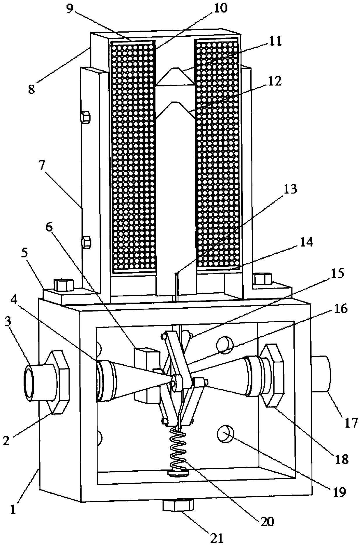
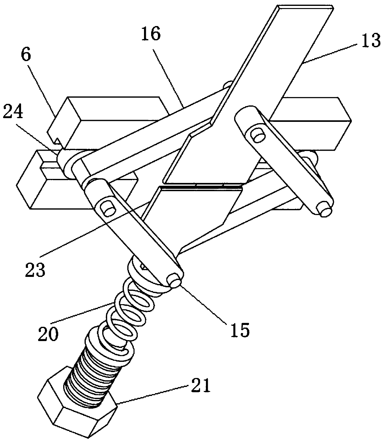
[0019] like figure 1 As shown, a non-contact electromagnetic pinch valve of the present invention includes a valve body 1, a pair of fixed plates 7 are vertically arranged on the upper surface of the valve body 1, and a fixed magnet 11 is installed between the pair of fixed plates 7, and the fixed magnet The outside of 11 is fitted with electromagnetic coil 10, the lower part of fixed magnet 11 is provided with a groove, the valve body 1 is provided with elastic pipe 22, one end of elastic pipe 22 is connected with the inlet of valve body 1, and the other end is connected with the outlet of valve body 1 Connection, the outside of the elastic pipe 22 is provided with a clamping device, the driving end of the clamping device protrudes from the outer wall of the valve body 1, the driving end is connected w...


PUM


Abstract

The invention discloses a non-contact type electromagnetic pinch valve. The non-contact type electromagnetic pinch valve comprises a valve body; a pair of fixing plates is perpendicularly arranged onthe upper surface of the valve body, a fixed magnet is mounted between the pair of fixing plates, an electromagnetic coil is mounted at the exterior of the fixed magnet in a sleeving mode, and a groove is formed in the lower part of the fixed magnet; an elastic pipeline is arranged in the valve body, one end of the elastic pipeline is connected with an inlet of the valve body, and the other end ofthe elastic pipeline is connected with an outlet of the valve body; a clamping device is arranged at the exterior of the elastic pipeline, and the driving end of the clamping device extends out of the outer wall of the valve body; and the driving end is connected with a movable magnet matched with the fixed magnet for moving, and the lower portion of the movable magnet is provided with a bulge matched with the groove. The non-contact type electromagnetic pinch valve solves the problem that an existing electromagnetic valve does not adapt to overcurrent control of a high-viscosity fluid.

Description

technical field [0001] The invention belongs to the technical field of valve control equipment, and in particular relates to a non-contact electromagnetic pinch valve. Background technique [0002] Most of the existing solenoid valves adopt the structure of gate valves, which generally have the following defects: (1) It will have a certain degree of hindrance to the flow of high-viscosity fluids, and the viscosity of the fluid itself is very likely to cause The solenoid valve is blocked; (2) For viscous fluids containing particles, it is easy to cause the valve core to be stuck and cannot be closed immediately during actual use; (3) When the work is stopped during mechanical maintenance, etc., the liquid is easy to adhere to the valve. Scabs on the core directly lead to valve failure; (4) The electromagnet of the solenoid valve is used as the driving force. Since the electromagnet has the working characteristic that the suction force drops sharply under a large gap, few sole...

Claims


Application Information

Patent Timeline
Patent Type & Authority Patents(China)
IPC IPC(8): F16K7/06F16K27/02F16K31/06
CPCF16K7/06F16K27/0236F16K31/0675
Inventor 郑勐何备林李恒胡艳凯
Owner XIAN UNIV OF TECH
Why Eureka
Try Eureka