Vehicle front part structure

a front part and vehicle technology, applied in vehicle components, superstructure subunits, transportation and packaging, etc., can solve the problems of large change in the basic frame of the vehicle, inability to prevent the front tire from giving an impact to the dash panel, and inability to prevent the front tire from direct impacting the dash panel, etc., to achieve enhanced safety

Active Publication Date: 2017-11-21
TOYOTA MOTOR KYUSHU +1
View PDF31 Cites 14 Cited by
  • Summary
  • Abstract
  • Description
  • Claims
  • Application Information

AI Technical Summary

Benefits of technology

[0008]When a front portion of a vehicle collides with something at the time of an offset collision or the like, the front tire which moves backward while going along an inner track by following a trajectory which draws an arc as described previously moves toward a dash panel between left and right lockers and front pillars and, depending on the behavior of the front tire, the front tire gives an impact to the dash panel so that a deformation amount of the dash panel is increased thus becoming one of factors which reduce a space of a cabin. Accordingly, giving an impact to the dash panel by the front tire is a state to be avoided from a viewpoint of ensuring safety of an occupant.
[0009]In this respect, it is considered that the constitution described in patent literature 1 can suppress the deformation of a front tire toward an area below the locker at the time of an offset collision. However, with respect to the behavior of the front tire which moves backward while going along an inner track by following a trajectory which draws an arc, it is not possible to prevent the front tire from giving an impact to the dash panel. In this manner, the prior art disclosed in patent literature 1 or the like has a drawback that it is impossible to prevent direct inputting of an impact of the front tire which moves backward while going along an inner track when a front portion of a vehicle collides with the dash panel at the time of an offset collision.
[0011]The present invention has been made in view of the above-mentioned circumstances, and it is an object of the present invention to provide a vehicle front part structure which can, without bringing about a large change in a basic frame of a vehicle, prevent a front tire which moves backward while going along an inner track when a front portion of the vehicle collides such as at the time of an offset collision or the like from giving an impact to a thin plate portion such as a dash panel thus enhancing safety.
[0015]According to the present invention, it is possible to prevent a front tire which moves backward while going along an inner track at the time of collision involving a front part of a vehicle such as at the time of an offset collision from giving an impact to a thin plate portion such as a dash panel so that safety can be enhanced without largely changing a basic frame of the vehicle.

Problems solved by technology

However, with respect to the behavior of the front tire which moves backward while going along an inner track by following a trajectory which draws an arc, it is not possible to prevent the front tire from giving an impact to the dash panel.
In this manner, the prior art disclosed in patent literature 1 or the like has a drawback that it is impossible to prevent direct inputting of an impact of the front tire which moves backward while going along an inner track when a front portion of a vehicle collides with the dash panel at the time of an offset collision.
These measures, however, bring about a large change in basic frame of the vehicle and hence, it is necessary to exchange parts per se with new parts or it is necessary to perform molding as an additional step whereby the introduction of these measures is difficult and is not suitable from a viewpoint of cost.

Method used


Image

  • Vehicle front part structure
  • Vehicle front part structure
  • Vehicle front part structure

Examples


first embodiment

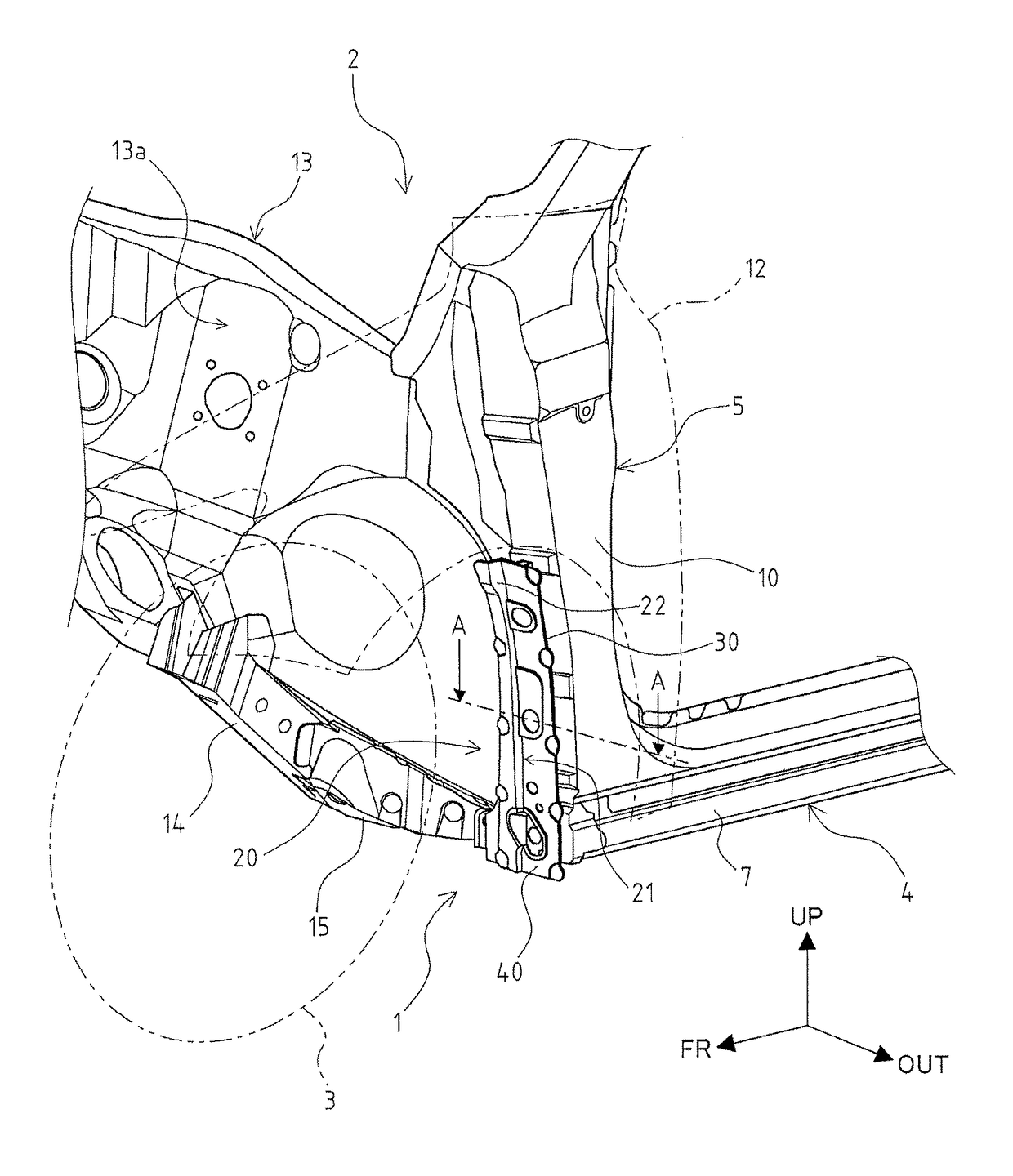
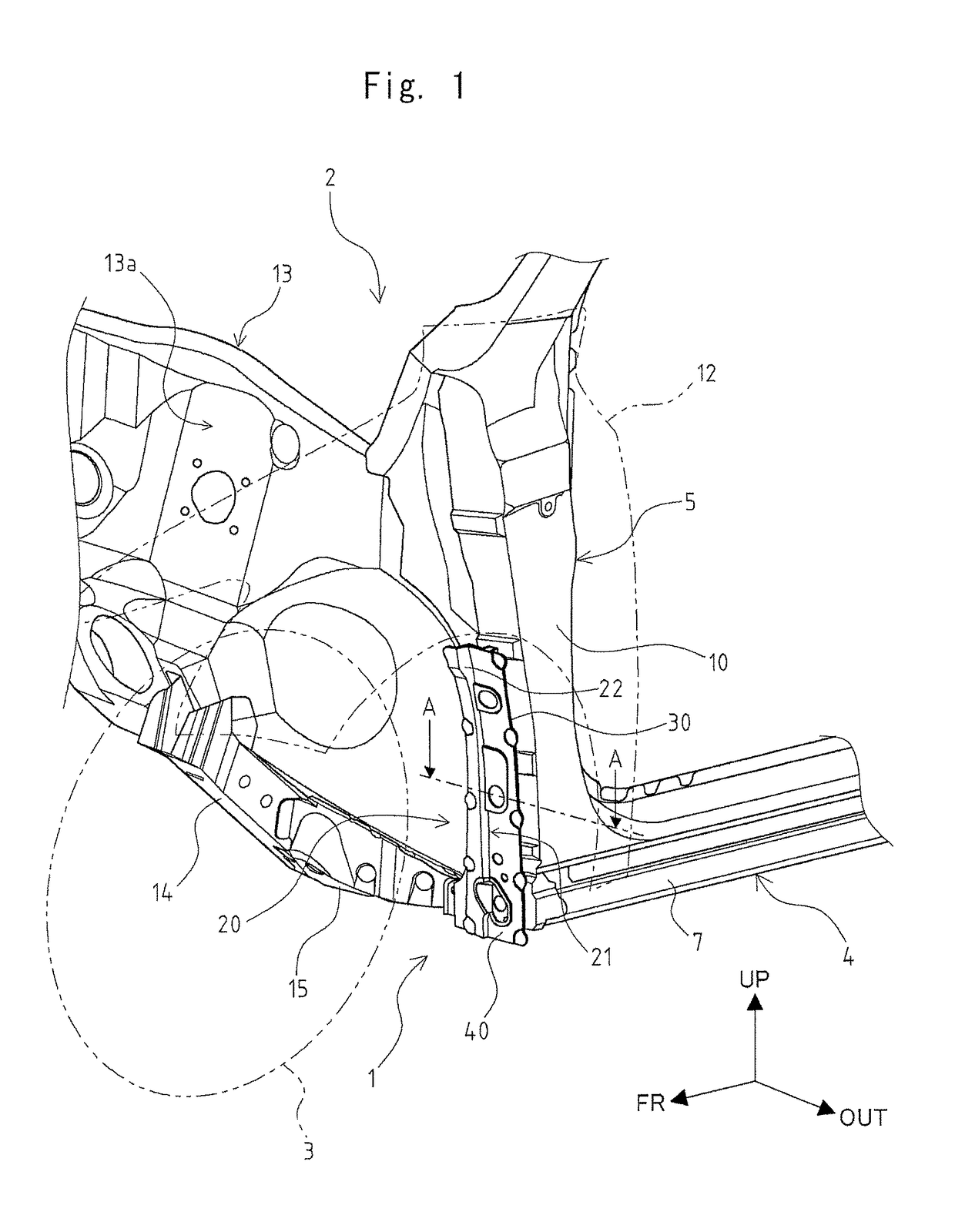
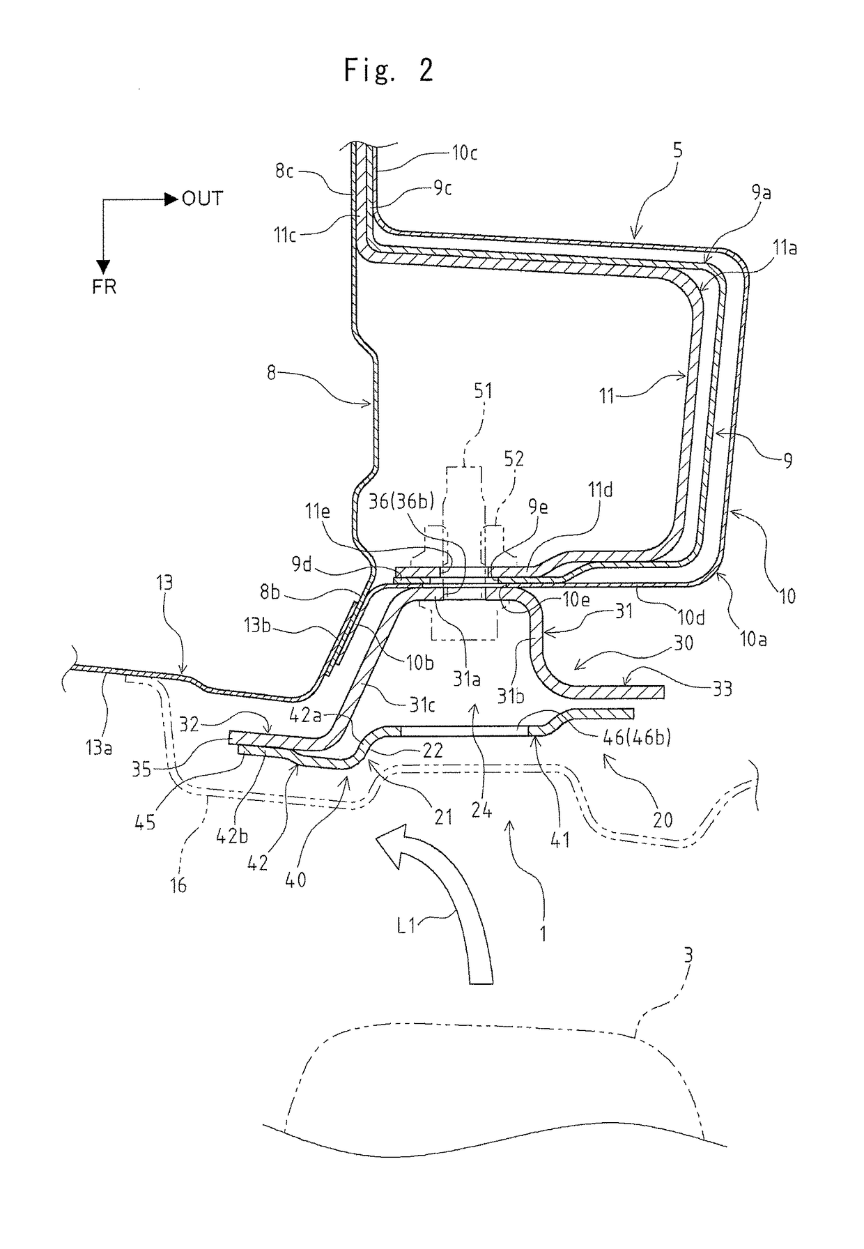
[0034]The first embodiment of the present invention is explained. As shown in FIG. 1 and FIG. 2, a vehicle front part structure 1 according to this embodiment is a structure of a lower part of a vehicle body positioned behind a front tire 3 of a vehicle 2 which is an automobile in the longitudinal direction of the vehicle body. FIG. 2 is a horizontal cross-sectional view showing the front structure of the vehicle 2, and corresponds to a cross-sectional view taken along a line A-A in FIG. 1 (corresponding to a line A′-A′ in FIG. 4).

[0035]The vehicle front part structure 1 includes a pair of left and right lockers 4 and a pair of left and right front pillars 5 in the vehicle 2. Both of the lockers 4 and the front pillars 5 are formed of a metal made member respectively.

[0036]The lockers 4 are arranged on both outer sides of a lower portion of the vehicle body of the vehicle 2 in the vehicle width direction with the longitudinal direction of the vehicle body set as the longitudinal dir...

second embodiment

[0158]The second embodiment of the present invention is explained by reference to FIG. 13 to FIG. 16. The explanation of parts which are substantially similar to the corresponding parts of the first embodiment is omitted when appropriate using the common or same symbols or the like. FIG. 14 is a horizontal cross-sectional view showing the front part structure of the vehicle 2 in the same manner as FIG. 2. FIG. 14 corresponds to a cross-sectional view taken along at a position D-D in FIG. 13 (corresponding to a position D′-D′ in FIG. 15).

[0159]As shown in FIG. 13 and FIG. 15, a gusset member 70 which the vehicle front part structure 61 according to this embodiment includes differs from the gusset member 20 of the first embodiment with respect to a point that the gusset member 70 includes an extension part 78 which expends toward an inner side in the vehicle width direction from a step forming portion 42 which forms a stepped portion 21 on a gusset front panel body portion 41. The ext...


PUM


Abstract

In a vehicle front part structure of a vehicle body, a gusset member is disposed in front of a front pillar. The gusset member is positioned so as to overlap with at least a front tire in the vertical direction of the vehicle body. The gusset member covers at least a portion of a lower portion of the front pillar on a front side in the longitudinal direction of the vehicle body. The gusset member has a stepped portion on a front side thereof in the longitudinal direction of the vehicle body. The stepped portion extends in the vertical direction of the vehicle body and makes a portion of the gusset member disposed inside in the vehicle width direction positioned relatively in front of a portion of the gusset member disposed outside in the vehicle width direction in the longitudinal direction of the vehicle body.

Description

BACKGROUND OF THE INVENTION[0001]Field of the Invention[0002]The present invention relates to a vehicle front part structure of a vehicle such as an automobile, and more particularly to a structure of a lower portion of a vehicle body positioned behind a front tire in the longitudinal direction of the vehicle body in a vehicle.[0003]Description of the Related Art[0004]As the vehicle front part structure of an automobile, there has been known the structure which includes: lockers arranged substantially horizontally with the longitudinal direction of the vehicle body set as the longitudinal direction of the lockers; and front pillars (A pillars) extending toward an upper side of the vehicle body from end portions of the locker on a front side in the longitudinal direction of the vehicle body on both outer sides of a lower portion of the vehicle body of the vehicle in the vehicle width direction. In such a structure, the front pillar extends in the vertical direction between a front gl...

Claims


Application Information

Patent Timeline
Patent Type & Authority Patents(United States)
IPC IPC(8): B62D25/04B62D25/14B62D25/02
CPCB62D25/025B62D25/14B62D25/04
Inventor TORIKAWA, YASUSHIKAJI, SHIGERUCHIBA, KENJI
Owner TOYOTA MOTOR KYUSHU
Why Eureka
Try Eureka