Supporting stand for display device

a technology for display devices and supports, which is applied in the direction of electrical apparatus casings/cabinets/drawers, casings with display/control units, and connection of coupling devices, etc. it can solve the problems of lack of cohesive (one-piece) feel in the appearance of the support, and the design is not propitious for releasing the display unit, so as to achieve easy separation

Active Publication Date: 2017-11-21
SYNCMOLD ENTERPRISE CORP
View PDF7 Cites 12 Cited by
  • Summary
  • Abstract
  • Description
  • Claims
  • Application Information

AI Technical Summary

Benefits of technology

[0007]An objective of the present invention is to provide a supporting stand for a display device, which is characterized by the provision of conductive portions at the location for mounting the display device. By virtue of the conductive portions for electrical connection with the display device mounted on the supporting stand, an electrical function unit built in the supporting stand can be electrically connected to the display device. Additionally, the conductive portions are also beneficial for a detachable supporting stand because the display device can be easily separated from the conductive portions of the supporting stand when detaching the display device therefrom.
[0009]Accordingly, the anode and cathode conductive portions of the bracket can be brought into abutment against the anode and cathode contacts of the display device, respectively, while mounting the display device on the bracket. As such, the display device in electrical contact with the anode and cathode conductive portions of the bracket can be electrically connected to the electrical function unit through the electrical connection unit, resulting in an electrical loop. Additionally, the association of the electrical connection unit with the bracket, but not with the display device, is advantageous to a detachable supporting stand. In particular, compared to the traditional plugging-in manner for electrical connection, the anode and cathode conductive portions can address quick connection / disconnection requirements and thus are more suitable for the supporting stand configured with quick-release capability. This is because the installation of the display device on the bracket would lead the display device to be electrical contact with the conductive portions of the bracket, without the need of any additional plugging-in action.
[0011]The aforementioned main plate can be designed into non-adjustable or rotatable type. In a preferred embodiment of the present invention, the main plate is configured to be rotatable in the mounting plane, so that the display device can be adjusted into portrait orientation, landscape orientation or other angle orientations by rotation of the main plate. For the aspect of the main plate being rotatable, the pin connector preferably is maintained stationary while rotation of the main plate. As a result, the stationary pin connector would not result in any undesired pulling on the electrical connection unit associated with the pin connector. Further, as the relative position of the pin connector at the open slot would change with rotary motion of the main plate, the display device may be provided with an additional anode contact for electrical connection with the pin connector when the display device is rotated to another orientation. For instance, the display device can be provided with two anode contacts for electrical contact with the pin connector when the main plate is placed at 0° and 90° orientation, respectively. Consequently, the display device in 0° (portrait) or 90° (landscape) orientation can be electrically connected to the electrical function unit at the base. Additionally, the open slot of the main plate preferably is shaped according to the relative motion trajectory between the pin connector and the main plate induced by the rotary motion of the main plate, so that the pin connector would not interfere with the rotary motion of the main plate. In accordance with a preferred embodiment of the present invention, the bracket further has a fixing plate and a shaft assembly, wherein the pin connector is fastened on the fixing plate, and the main plate and the fixing plate are pivotally attached to the shaft assembly. At a result, the main plate can rotate about the shaft assembly, and the fixing plate is maintained stationary while rotation of the main plate.
[0012]In the present invention, the anode / cathode conductive portions of the bracket can be electrically coupled to the electrical connection unit in any manner without particular limitation, as long as the electrical connection unit can provide electrical connection between the anode / cathode conductive portions and the electrical function unit. For instance, in accordance with a preferred embodiment of the present invention, the electrical connection unit has a first cable electrically connected to the pin connector and a second cable electrically connected to an electrical joint structure of the fixing plate. The electrical joint structure is placed in electrical contact with the main plate so as to provide electrical connection between the main plate and the second cable. As both opposite ends of the electrical connection unit are coupled with components of the supporting stand (namely, one end of the electrical connection unit being connected to the electrical function unit, and the other end being connected to the anode and cathode conductive portions of the bracket), the electrical connection unit can be integrated into the interior of the supporting stand so as to avoid exposed cables and give the supporting stand a cohesive (one-piece) feel. Preferably, the electrical connection unit includes a main cable received in the interior of the upright. Specifically, the main cable extends along the upright and has one end electrically connected to the electrical function unit and an opposite end electrically connected to the first and second cables. For the main cable, the first cable and the second cable, the selection of cable types can be made according to the requirement without particular restriction. In consideration of easy routing of the main cable received within the upright, the main cable preferably is a flexible cable.
[0015]In the present invention, the holding unit can be configured as adjustable or non-adjustable in height according to requirement. Preferably, the holding unit is adjustable in height and can slide upward and downward in a channel formed in the upright. Accordingly, the display device can be adjusted to desired height for comfortable viewing. Further, in order to avoid breaking of the electrical connection unit caused by lifting and lowering motion of the holding unit, the main cable preferably has a free section corresponding to the channel. The free section of the main cable can be forced into bending and thus be adapted to the sliding motion of the holding unit.

Problems solved by technology

As both opposite ends of the cable are directly coupled to the interface circuit board and the main circuit board without any connectors for detachable attachment, the design is not propitious for releasing the display unit from the stand unit.
However, the external cable extending from the base of the stand to the display device would cause lack of cohesive (one-piece) feel in the appearance of the stand, and even be easily pulled and broken due to improper or inadvertent operation.

Method used


Image

  • Supporting stand for display device
  • Supporting stand for display device
  • Supporting stand for display device

Examples


Embodiment Construction

[0024]Hereafter, example will be provided to illustrate the embodiments of the present invention. Advantages and effects of the invention will become more apparent from the disclosure of the present invention. It should be noted that these accompanying figures are simplified and illustrative. The quantity, shape and size of components shown in the figures may be modified according to practical conditions, and the arrangement of components may be more complex. Other various aspects also may be practiced or applied in the invention, and various modifications and variations can be made without departing from the spirit of the invention based on various concepts and applications.

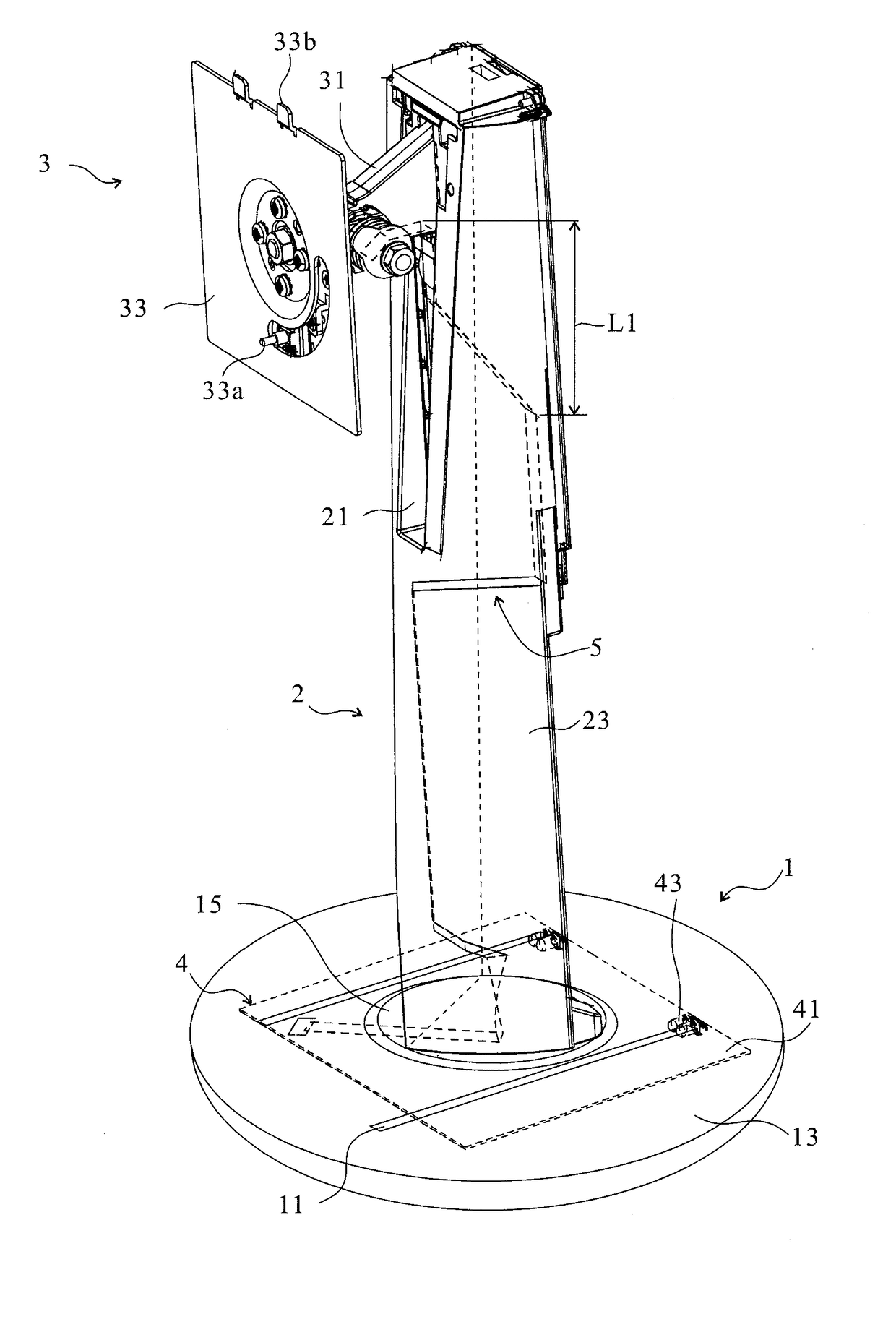
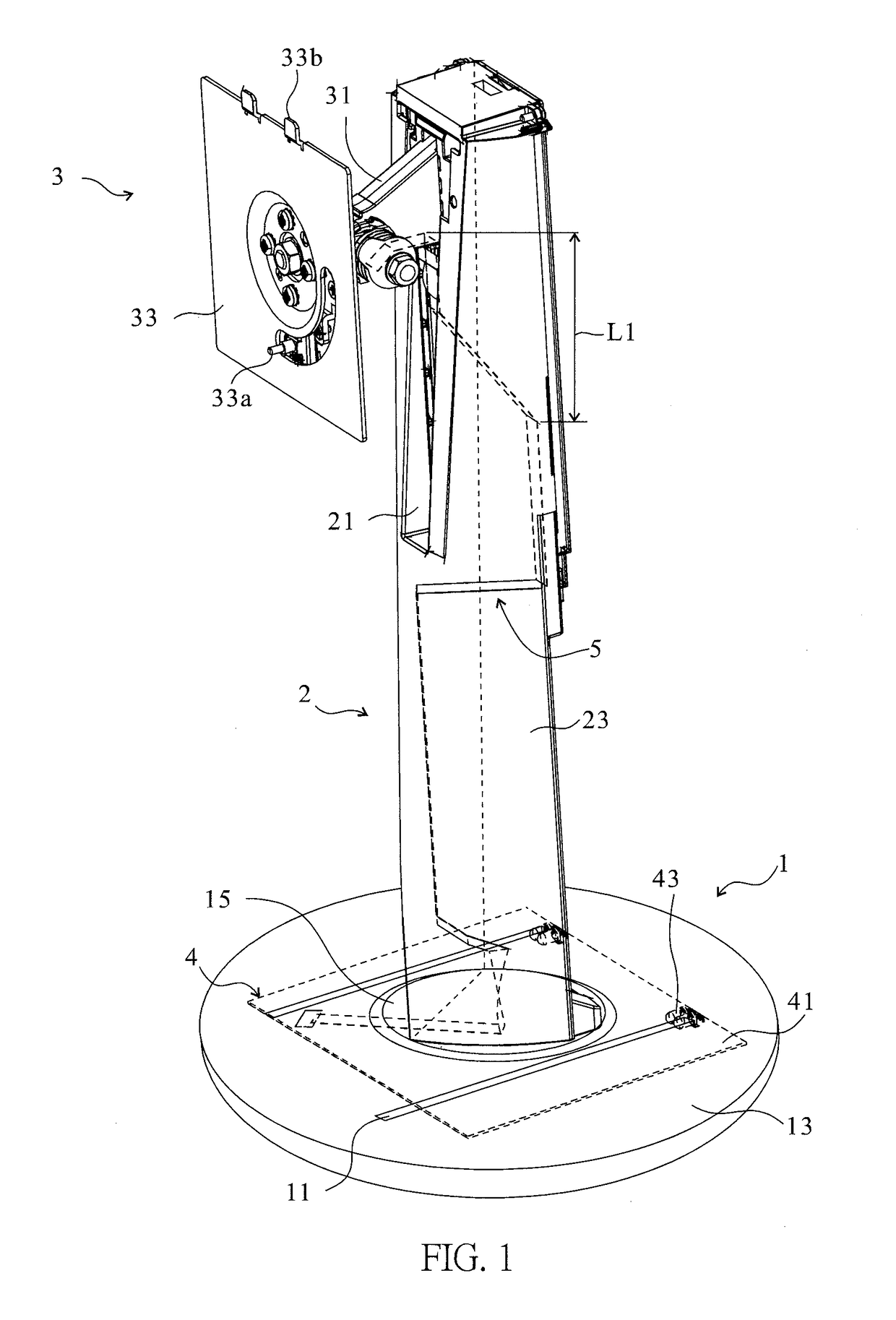
[0025]Please refer to FIG. 1, which is a perspective schematic view of a supporting stand 1000 in accordance with one embodiment of the present invention. The supporting stand 1000 of this embodiment includes abase 1, an upright 2, a holding unit 3, an electrical function unit 4 and an electrical connection unit...


PUM


Abstract

Disclosed is a supporting stand for a display device, which includes: a base; an upright connected to the base; a holding unit connected to the upright and including a bracket, wherein the bracket has an anode conductive portion and a cathode conductive portion to provide electrical contacts for the display device; an electrical function unit disposed within the base; and an electrical connection unit electrically connecting the electrical function unit to the anode and cathode conductive portions of the bracket. Accordingly, the display device can be disposed in contact with the anode and cathode conductive portions of the bracket when being mounted on the bracket, and be electrically connected to the electrical function unit at the base by the electrical connection unit.

Description

CROSS REFERENCE TO RELATED APPLICATION[0001]This application claims the benefits of the Taiwan Patent Application Serial Number 104213500, filed on Aug. 21, 2015, the subject matter of which is incorporated herein by reference.BACKGROUND OF THE INVENTION[0002]1. Field of the Invention[0003]The present invention relates to a supporting stand and, more particularly to, a supporting stand provided with conductive portions at the location for mounting a display device.[0004]2. Description of Related Art[0005]Disclosed in U.S. Pat. No. 6,268,997 B1 is a flat-panel display apparatus that includes a display unit and a stand unit with an interface circuit board and a speaker installed in its base. By virtue of a cable, the interface circuit board is electrically connected to a main circuit board in the display unit. As both opposite ends of the cable are directly coupled to the interface circuit board and the main circuit board without any connectors for detachable attachment, the design is...

Claims


Application Information

Patent Timeline
Patent Type & Authority Patents(United States)
IPC IPC(8): H05K7/00H05K5/02H05K5/00F16M11/04H01R33/05F16M11/10F16M11/20H01R33/94F16B1/00
CPCF16M11/041F16M11/046F16M11/10F16M11/105F16M11/2014H01R33/94H05K5/0017H05K5/0234H05K5/0247H01R33/05F16B2001/0064F16M11/24F16M2200/065F16M11/2064F16B2200/93
Inventor CHEN, KUANG-POTING, KUN-TIENLIU, WEN-CHENSHIH, LI-WEI
Owner SYNCMOLD ENTERPRISE CORP
Why Eureka
Try Eureka