
Dynamic control loop for switching regulators

a technology of switching regulators and dynamic control loops, applied in the field of regulators, can solve the problems of adding design complexity, not providing the highest power efficiency, and , the response time to transient supply and load current is slow

Active Publication Date: 2017-11-21
TAIWAN SEMICON MFG CO LTD
View PDF16 Cites 1 Cited by
  • Summary
  • Abstract
  • Description
  • Claims
  • Application Information

AI Technical Summary

Benefits of technology

The patent text describes a switching regulator that can dynamically adjust the pulse width or duty cycle of pulses used to convert DC-to-DC voltage, which can improve power efficiency. The regulator can also adapt to changes in input voltage, output voltage, load conditions, and components driven by the regulator. The use of a digital approach to calculate the pulse width can further increase power efficiency compared to other methods. Additionally, the patent discusses how the regulator can adjust the output voltage based on dynamic voltage frequency scaling (DVFS) to save power. These technical features and advantages can make the regulator more efficient, save battery life, and improve the overall performance of electronic devices.

Problems solved by technology

For example, in one approach, the feedback loop includes two comparators receiving two reference voltages as inputs, which adds design complexities, but does not provide the highest power efficiency (e.g., η).
The response time to transients on supply and load current, however, is slow, and the dynamic adjustment is not available.

Method used


Image

  • Dynamic control loop for switching regulators
  • Dynamic control loop for switching regulators
  • Dynamic control loop for switching regulators

Examples


Embodiment Construction

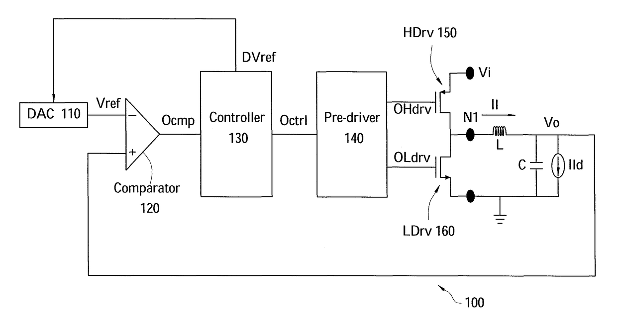
[0012]Embodiments, or examples, illustrated in the drawings are now disclosed using specific language. It will nevertheless be understood that the embodiments and examples are not intended to be limiting. Any alterations and modifications in the disclosed embodiments, and any further applications of the principles disclosed in this document are contemplated as would normally occur to one of ordinary skill in the pertinent art. Reference numbers may be repeated throughout the embodiments, but they do not require that feature(s) of one embodiment apply to another embodiment, even if they share the same reference number.

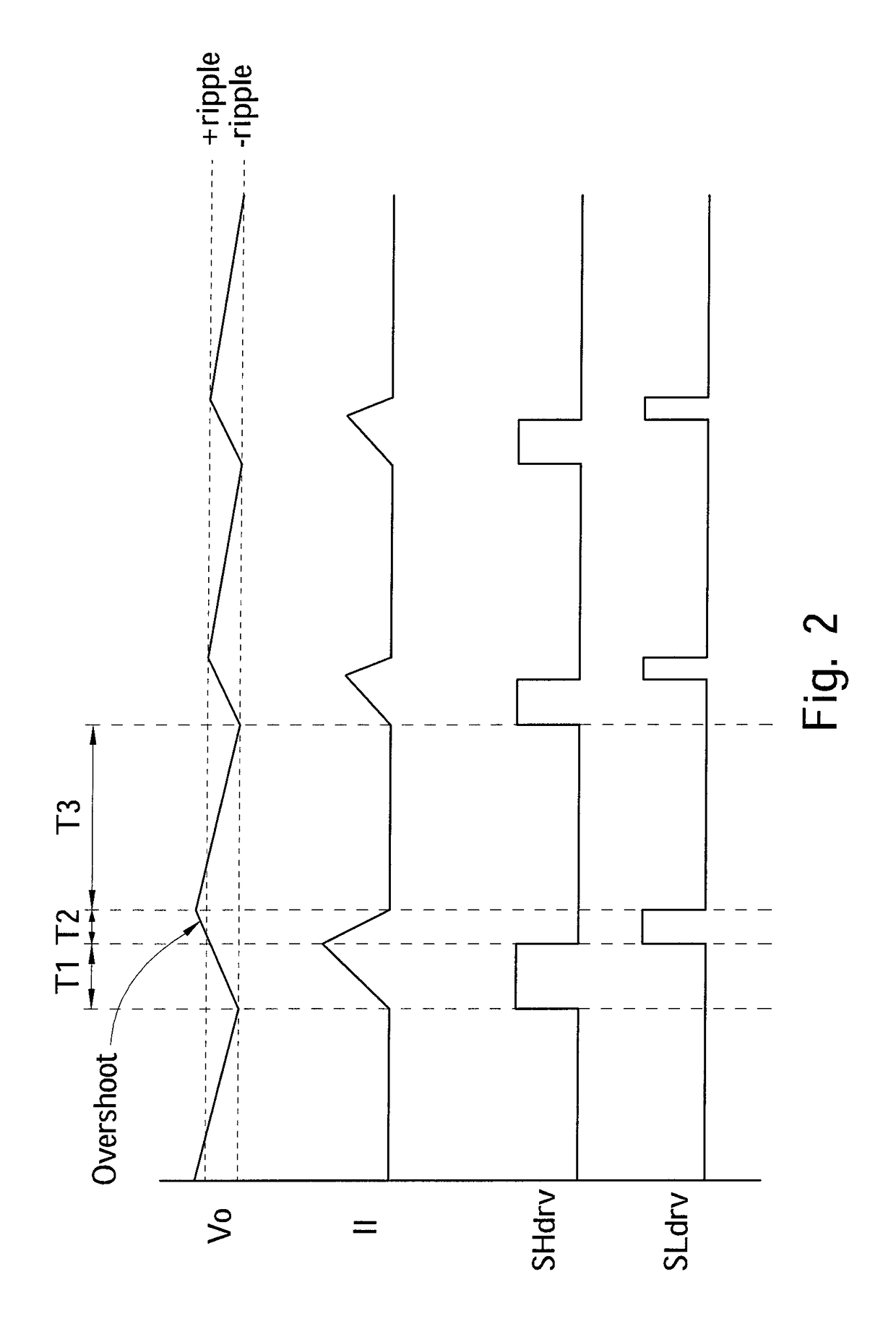
[0013]Some embodiments can have one or a combination of the following features and / or advantages. In some embodiments, dynamic adjustment of the pulse width or the duty cycle of pulses used in converting the DC-to-DC voltage in light current loads is available to optimize power efficiency. In some embodiments, the output voltage of the switching regulator is controlled ...


PUM


Abstract

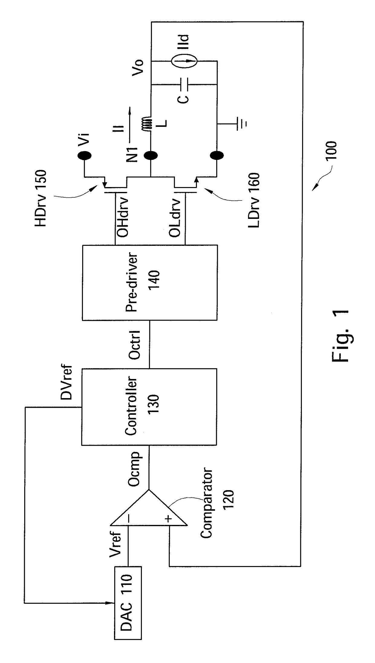
A regulator includes a controller, a driving unit, a digital-to-analog converter, and a comparator. The controller outputs a digital reference voltage and a control signal responsive to a comparison signal. The driving unit generates an output voltage at a first node responsive to the control signal. The digital-to-analog converter generates an analog reference voltage responsive to the digital reference voltage. The comparator generates the comparison signal based on the analog reference voltage and the output voltage.

Description

PRIORITY CLAIM[0001]This application is a continuation of U.S. application Ser. No. 12 / 856,918, filed Aug. 16, 2010, the disclosure of which is incorporated herein by reference in its entirety.FIELD[0002]The present disclosure is generally related to regulators, and more particularly to a dynamic control loop for switching regulators.BACKGROUND[0003]Switching regulators or direct-current to direct-current (DC-DC) voltage converters (i.e., DC-DC converters) commonly include a pulse frequency modulation (PFM) component in a feedback loop having pre-determined reference voltages and comparators. For example, in one approach, the feedback loop includes two comparators receiving two reference voltages as inputs, which adds design complexities, but does not provide the highest power efficiency (e.g., η). Power efficiency η is defined as the ratio of the output power (e.g., Po) over the input power (e.g., Pi) wherein the input power Pi is equal to the output power Po plus the dissipated po...

Claims


Application Information

Patent Timeline
Patent Type & Authority Patents(United States)
IPC IPC(8): H02M3/157H02M3/04H02M3/156H02M1/00
CPCH02M3/04H02M3/156Y02B70/16H02M2001/0032Y02B70/10H02M1/0032
Inventor SHI, JUSTINROTH, ALANGAITHER, JUSTINSOENEN, ERIC
Owner TAIWAN SEMICON MFG CO LTD
Learn More