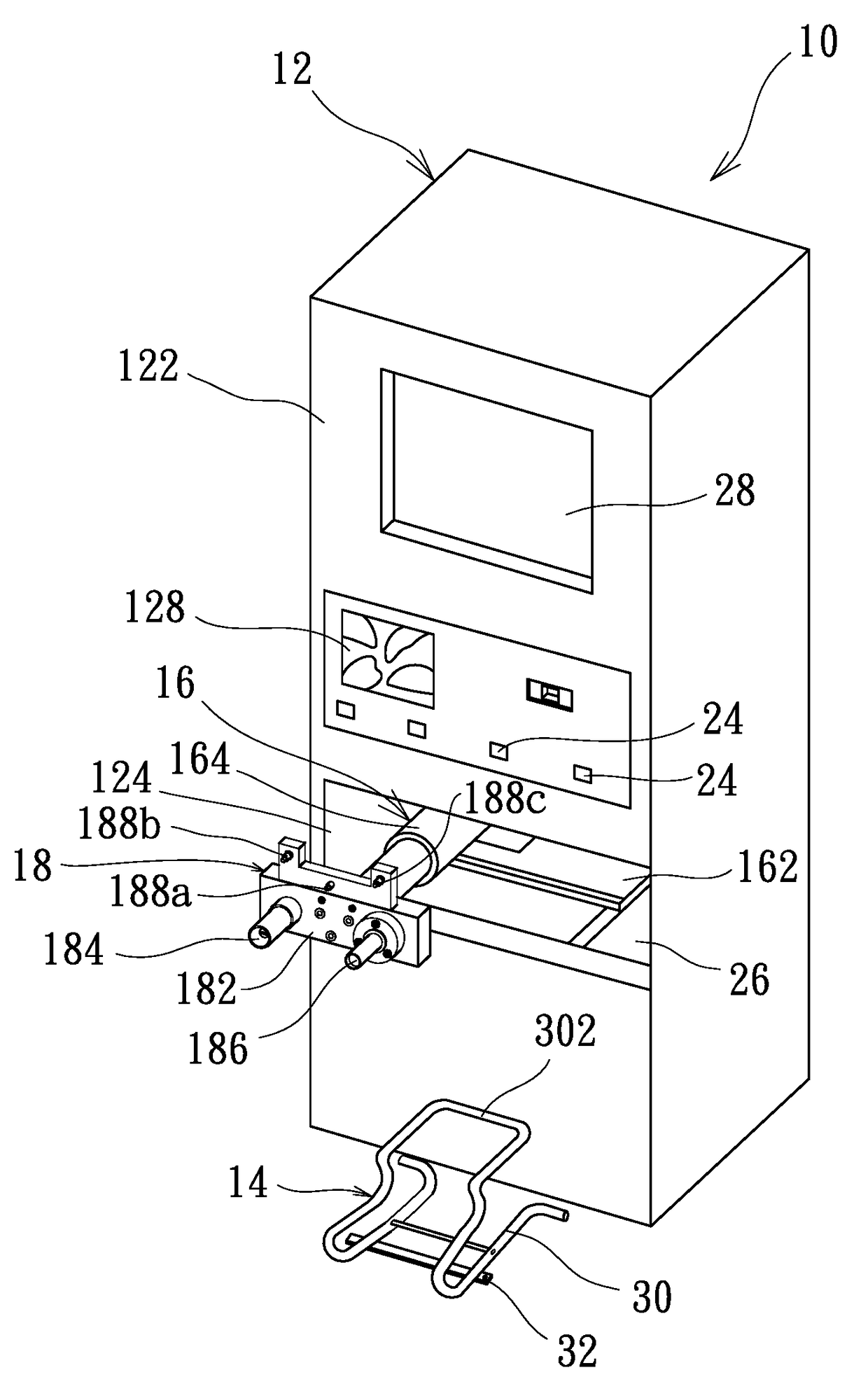
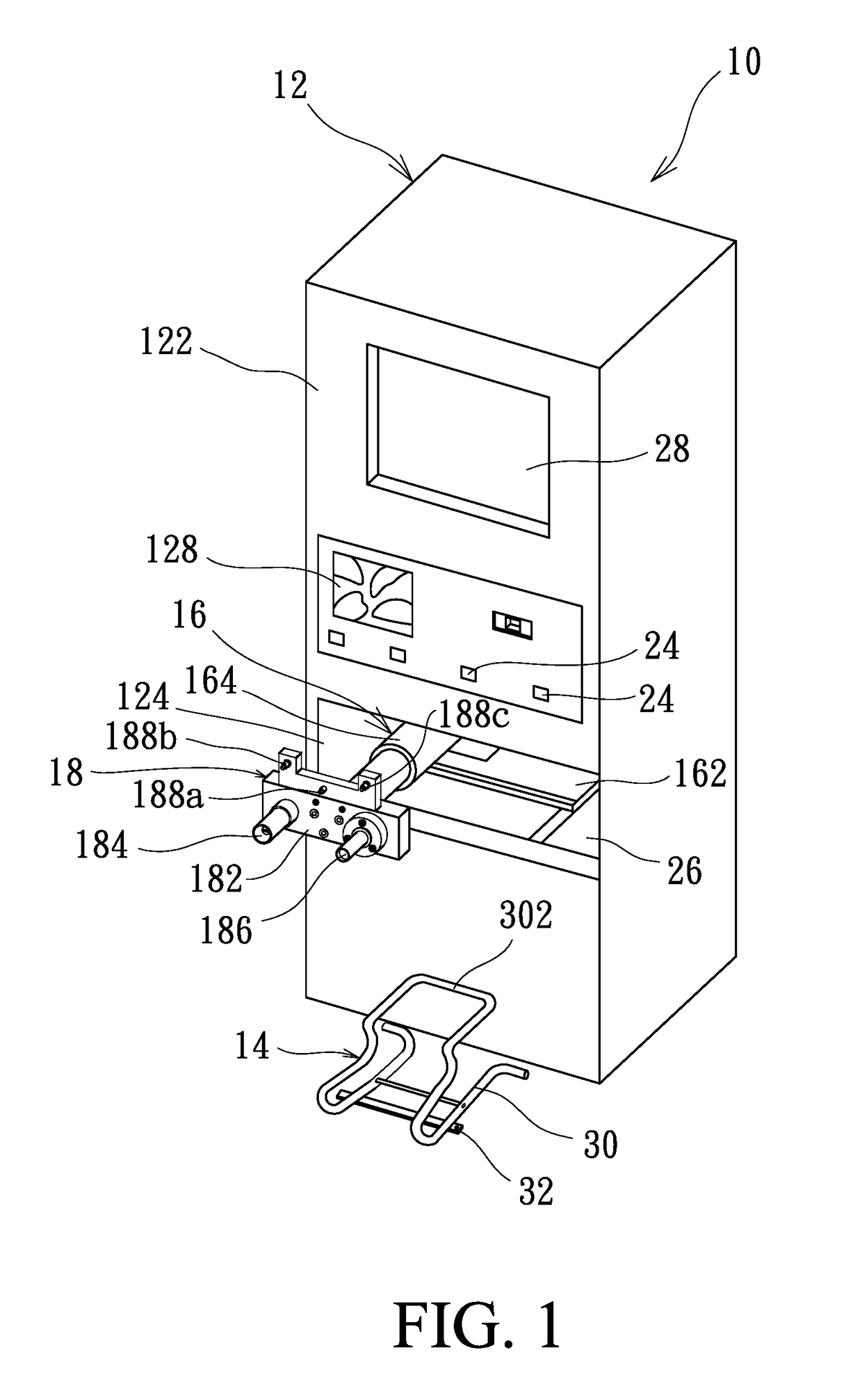
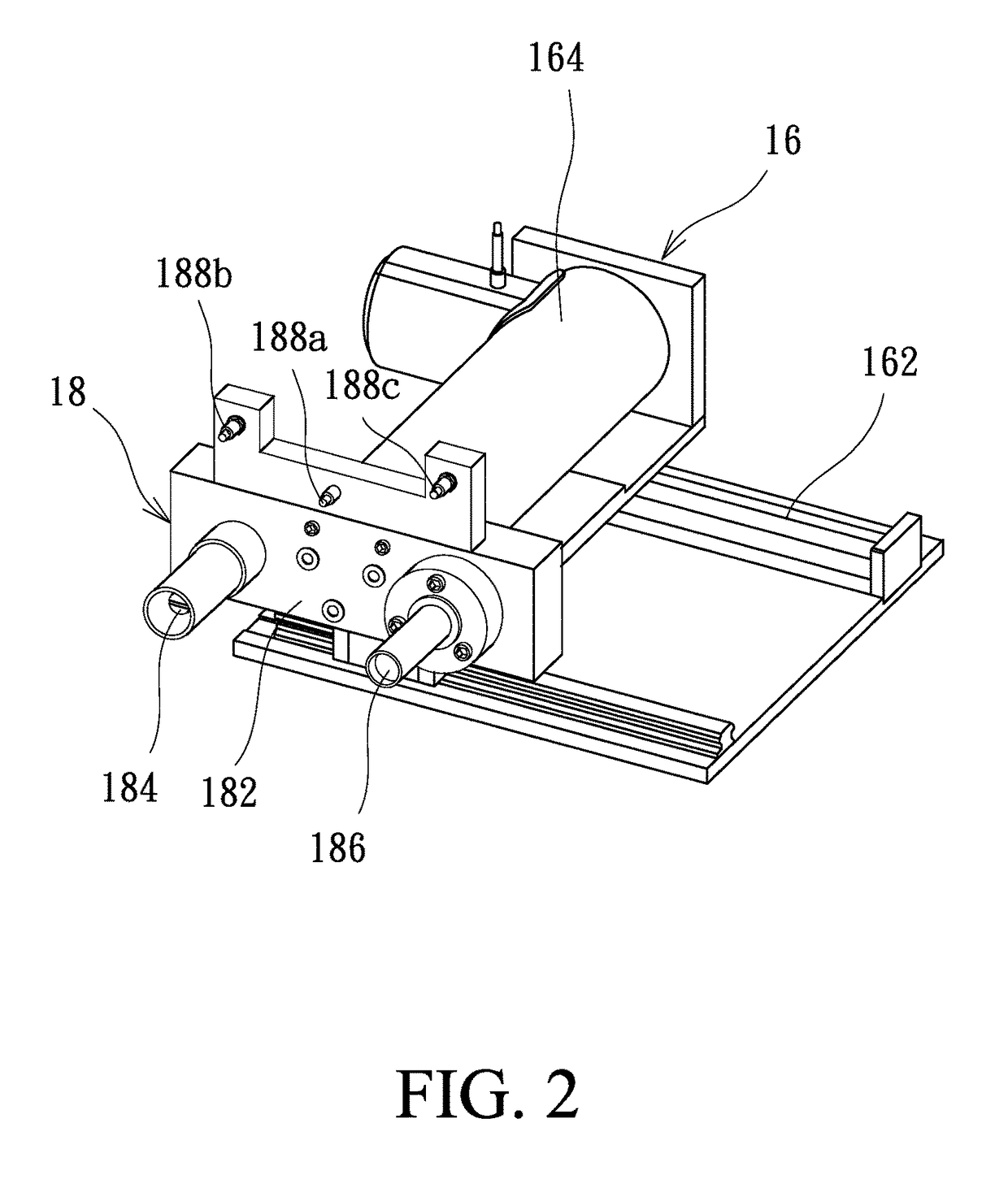
Charging system and charging connector thereof

a charging system and connector technology, applied in the direction of electric devices, cycles, transportation and packaging, etc., can solve the problems of difficult to provide an insulating space between the positive terminal and the negative terminal of the conventional cable-type charging connector, and achieve the effect of saving manpower costs

Active Publication Date: 2017-11-28
HWANG HONG WEN
View PDF3 Cites 2 Cited by
  • Summary
  • Abstract
  • Description
  • Claims
  • Application Information

AI Technical Summary

Benefits of technology

[0007]An object of the invention is to provide a charging system and a charging connector thereof. The charging system is capable of securing the tire of an electric vehicle and automatically detecting the chargeable positions of the electric vehicle, so that the charging connector can be automatically coupled to the chargeable positions of the electric vehicle. As the position of the electric vehicle is fixed, the electric vehicle can be electrically charged. In this manner, the charging service provider can save manpower cost. Compared to the conventional charging station or battery exchange station, the invention can protect the user from being electrically shocked and prevent the electric vehicle from getting short-circuited or suffering from electrical leakage.
[0008]Another object of the invention is to provide a charging system and the charging connector thereof. The invention is featured by isolating the positive charging plug and the negative charging plug, thereby providing isolation between the positive charging plug and the negative charging plug. As is known in the prior art, it is difficult to provide an insulating space for the positive terminals and the negative terminals within the conventional cable-type charging connector. The invention is capable of suppressing this disadvantage by isolating the positive charging terminals and the negative charging terminals by providing a positive cable-type charging plug and a negative cable-type charging plug. By disallowing the positive terminals of the charging connector from contacting the negative terminals of the charging connector, the user can be protected from being electrically shocked and the electric vehicle can be protected from getting short-circuited. Thus, the convenience of the charging operation can be enhanced. Moreover, as the magnitude of the charging current flowing through the cable-type charging connector is as high as several amperes, the isolated disposition of the positive charging plug and the negative charging plug is efficient in reducing the electromagnetic interference.
[0009]Another yet object of the invention is to provide a charging system and the charging connector thereof. The charging system is featured by saving the waste of manpower, providing an easy-to-user interface, enhancing the safety level of the charging operation. The invention is capable of providing a positioning module for allowing the user to push the electric vehicle to the front of the charging stand and easily secure the electric vehicle in front of the charging stand for proceeding with the charging operation. Thus, the charging procedure can be simplified. The user may move the electric vehicle away from the charging stand after the payment procedure is finished, so as to simplify and facilitate the charging operation.

Problems solved by technology

As is known in the prior art, it is difficult to provide an insulating space for the positive terminals and the negative terminals within the conventional cable-type charging connector.

Method used


Image

  • Charging system and charging connector thereof
  • Charging system and charging connector thereof
  • Charging system and charging connector thereof

Examples


Embodiment Construction

[0028]Several exemplary embodiments embodying the features and advantages of the invention will be expounded in following paragraphs of descriptions. It is to be realized that the present invention is allowed to have various modification in different respects, all of which are without departing from the scope of the present invention, and the description herein and the drawings are to be taken as illustrative in nature, but not to be taken as a confinement for the invention.

[0029]With the advent of electric vehicles, various kinds of electric vehicles, such as electric automobiles and electric motorcycles, have been produced. The development of electric vehicles has encountered some bottlenecks that need to be overcome, for example, the limited amount of electricity stored in the batteries, the slow charging rate of the battery, and the scant battery exchange facility. The invention is capable of enhancing the stability and automation level of the charging operation and adapting the...


PUM


Abstract

Provided is a charging system and a charging connector thereof. The charging system includes a charging stand, a positioning module mounted in front of the front surface of the charging stand for securing the tire of an electric vehicle, and a moving module mounted within and connected to the charging stand. The charging connector includes a positive charging plug and a negative charging plug located on the moving module. The charging connector is connected to the charging stand. When the electric vehicle is secured by the positioning module, the charging stand detects the type of the battery of the electric vehicle and drives the moving module to move outside the charging stand, so that the positive charging plug and the negative charging plug that are isolated from each other are connected to the chargeable positions of the electric vehicle, thereby forming a charging loop.

Description

BACKGROUND OF THE INVENTION[0001]Field of the Invention[0002]The invention is related to a system for securing and charging electric vehicle, and more particularly to a charging system with a positive charging plug and a negative charging plug being isolated from each other and the charging connector thereof.[0003]Description of the Prior Art[0004]With the aggravation of greenhouse effect and the energy crisis, vehicles have to change their energy supply from the petrochemical energy to the electrical energy. It is a tendency that the electric vehicles are becoming more and more popular. The energy crisis has contributed to the mushroom development of electric automobiles and electric motorcycles. As a result, the development of the charging technique for supplying electrical energy to electric vehicles has achieved significant progress.[0005]The charging station, for example, is designed for supplying electric energy for electric vehicle, like the gas station. The charging station ...

Claims


Application Information

Patent Timeline
Patent Type & Authority Patents(United States)
IPC IPC(8): H02J7/00B60L11/18H01R13/73
CPCB60L11/1818H01R13/73B60L11/1824B60L3/0023B60L2200/12B60L53/16B60L53/305B60L53/35Y02T10/70Y02T10/7072Y02T90/12Y02T90/14Y02T90/16
Inventor HWANG, HONG-WEN
Owner HWANG HONG WEN
Why Eureka
Try Eureka