Reversible polarity MPO fiber optic connector

a fiber optic connector and polarity technology, applied in the field of fiber optic connectors, can solve the problems of increasing labor costs or material costs associated with these networks/connectors, and achieve the effects of reducing installation time, reducing installation costs, and reducing installation costs

Active Publication Date: 2017-11-28
US CONEC
View PDF9 Cites 59 Cited by
  • Summary
  • Abstract
  • Description
  • Claims
  • Application Information

AI Technical Summary

Benefits of technology

[0017]The present arrangement overcomes the drawbacks associated with the prior art and provides for a reversible polarity MPO type connector that can be applied without worry of previous installation types or designs. The reversible polarity connector reduces installer's and customer's inventory, installation time, and ultimately lowers their cost.
[0018]Such a connector employs a movable key that allows a user to reverse the polarity of the connector without the need to open the connector housing. Additionally, the present connector can be employed in conjunction with a universal connector pin arrangement that also allows a user to push forward or retract the MPO guide pins to assist in accommodating the use of such connectors in both polarities, again without the need for opening the connector.

Problems solved by technology

Although some prior art arrangements have the ability to change the key / polarity of the connector, these solutions require the disassembling and reassembling of existing assemblies or the purchase of new assemblies.
This increases either labor costs or material costs associated with these networks / connectors.

Method used


Image

  • Reversible polarity MPO fiber optic connector
  • Reversible polarity MPO fiber optic connector
  • Reversible polarity MPO fiber optic connector

Examples


Embodiment Construction

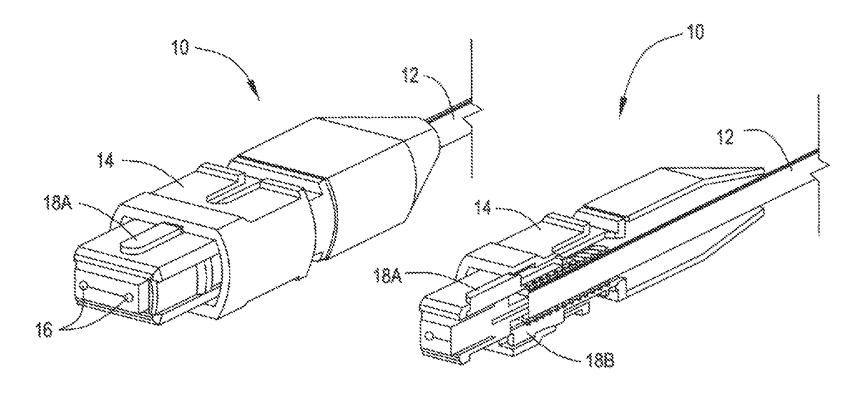
[0032]In one embodiment of the present arrangement as shown in FIGS. 4A and 4B a connector 10 is provided at the end of a multi fiber cable 12. Connector 10 has a housing 14, guide pins / guide pin openings 16 and keys 18A and 18B. It is noted that connector 10 is shown with guide pin openings 16 (female) but all of the features of the present arrangement are equally applicable to male / pins extended connectors 10 as well.

[0033]As a basic explanation the “key” sets the order for which the fibers in connector 10 are presented to an additional opposing connector 10. A key that is ‘active’ is one that is in position to engage with an adapter. If a key is said to be reversed then it means that the key on the opposite side of the connector (that being the one that was not previously ‘active’) is now ‘active’. If connectors of both regular and reversed active keys are compared, it would be found that the fibers in connector 10 are presented to an opposing connector in opposite order. The set...


PUM


Abstract

A multi-fiber, fiber optic connector is provided having a housing having a first end for receiving a multi-fiber fiber optic cable and a second end having openings for the fibers from the cable. First and second keys for setting the polarity of the fibers within the connector located on opposing sides of the connector. The connector has either one of guide pins or guide pin receiving holes for guiding the connection with a second connector. The keys are movable between a first active position and a second retracted position, such that when one of the keys is in the first active position, the fibers are presented within the connector in a first polarity and when the second key is in the first active position, the fibers are presented within the connector in a second polarity reversed from the first polarity.

Description

RELATED APPLICATION[0001]This application is related to U.S. patent application Ser. No. 13 / 934,378, filed on Jul. 3, 2013.BACKGROUND[0002]Field of the Invention[0003]The present arrangement relates to fiber optic connectors. More particularly, the present arrangement relates to fiber optic connectors with reversible polarity.[0004]Description of the Related Art[0005]In the area of fiber optic connections, typical fiber optic systems usually have to establish a bi-directional pathway between a transmitter port on a first element and receiver port on a second element and vise versa. See for example schematic FIG. 1. In order for such a bidirectional systems to function, it is a requirement that one end of a fiber be connected to the light emitting source of a first equipment, often a type of laser or light emitting diode, and the other end connected to a receiver port on a second equipment. For the second fiber in the bi directional pathway, the other fiber needs to be connected to t...

Claims


Application Information

Patent Timeline
Patent Type & Authority Patents(United States)
IPC IPC(8): G02B6/38
CPCG02B6/3831G02B6/3851G02B6/3885G02B6/3883G02B6/3882
Inventor GOOD, PAUL MICHAELAYRES, III, WILLIAM E.HEFFNER, GREG
Owner US CONEC
Why Eureka
Try Eureka