
Apparatus and method for manufacturing particles

a technology of apparatus and particles, applied in the direction of gas-gas reaction process, transportation and packaging, oxygen/ozone/oxide/hydroxide, etc., can solve the problems of high production rate, high energy consumption of materials at such high temperatures, and high labor intensity of workers, etc., to achieve the effect of high production ra

Active Publication Date: 2017-12-05
REACTIVE METAL PARTICLES
View PDF25 Cites 1 Cited by
  • Summary
  • Abstract
  • Description
  • Claims
  • Application Information

AI Technical Summary

Benefits of technology

[0018]The objective of the present invention is to provide a method and apparatus for manufacturing solid particles in a manner which is scalable, reproducible and economical at high production rates.
[0019]It is further an objective of the invention to provide a method and apparatus for manufacturing solid particles with external diameters in the micron-, submicron- or nanoscale in a manner which is scalable, reproducible and economical at high production rates.DESCRIPTION OF THE INVENTION
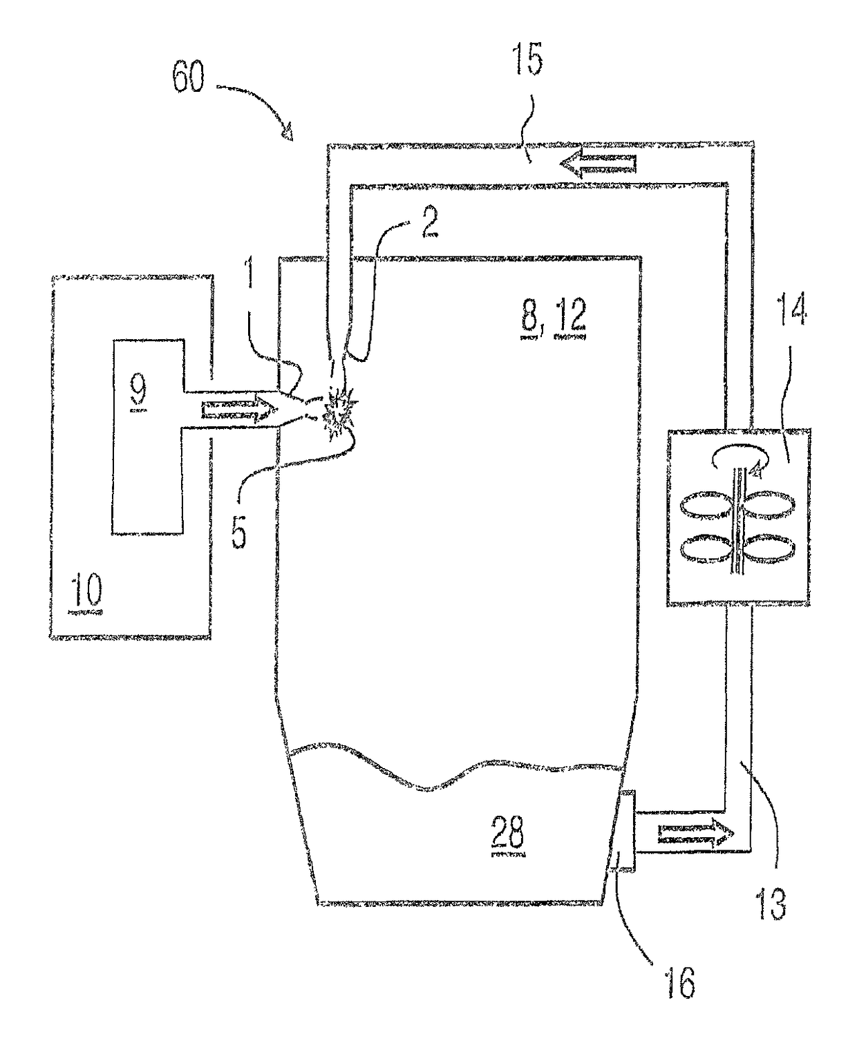
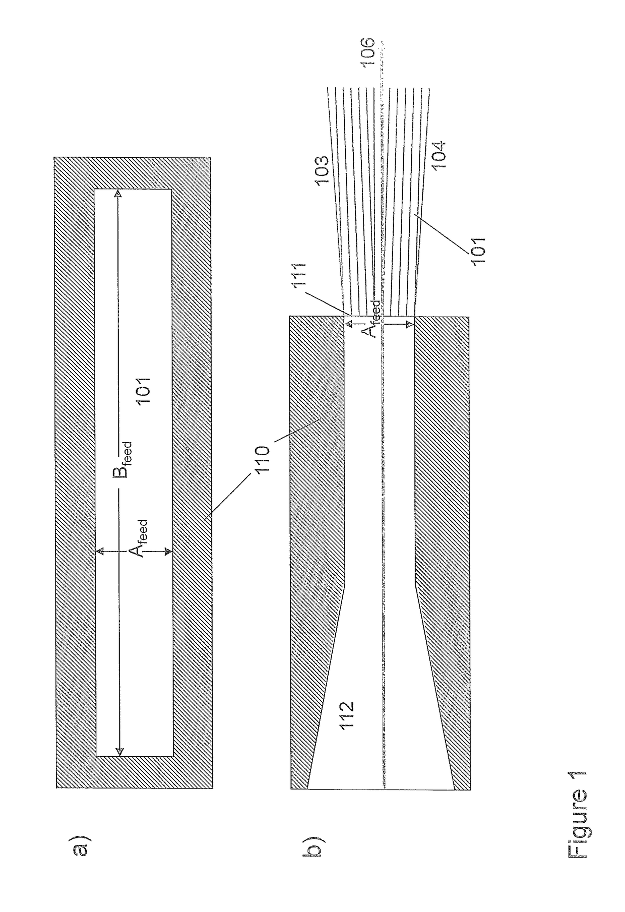
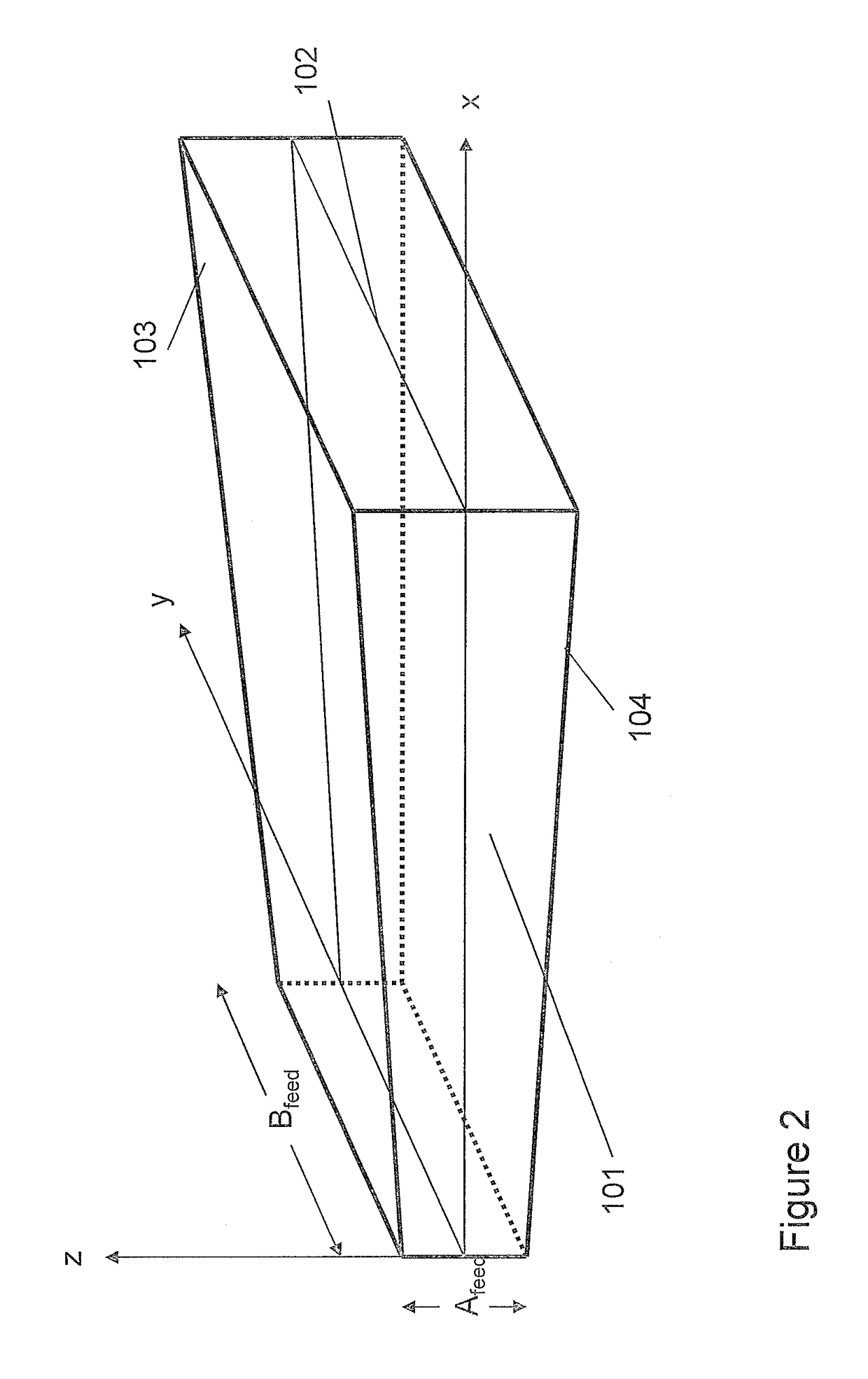
[0020]The present invention is a utilisation of the realisation that the very strict control of the gradients of mass, temperature and pressure required for manufacturing small, such as i.e. nanosized, particles with narrow size distributions by condensation from a gas phase, may be obtained for large volume flows by keeping the necessary small size in one characteristic dimension of the reaction zone and obtain the flow volume increase by expanding in another characteristic dimension. That, is by employing a specific nozzle design, it becomes possible to substantially increase the production volumes by increasing the volume flow and still maintain the required gradients of mass, temperature and pressure in the precipitation zone required to form i.e. nanosized, or larger, particles.

Problems solved by technology

Aforementioned known methods of manufacturing nanoparticles often employ material vapours in a temperature range of 5000 to 10000 K; heating materials to such high temperatures is very energy intensive.
Moreover, use of such high temperatures has an undesirable drawback that any contaminants that are present in raw material employed will be transferred over to corresponding manufactured nanoparticles.
The article informs that these processes often happen rapidly, in a matter of milliseconds and often at a relatively uncontrolled fashion.
However, the need of strict control with the gradient has hitherto been difficult to combine with the desire for up-scaling production lines to obtain an “economy of scale” effect, for the production of very small particles such as sub-micron and nanoparticles, since larger flow volumes means larger dimensions of the reactor and thus reduced control with the gradients in the reaction zone.

Method used


Image

  • Apparatus and method for manufacturing particles
  • Apparatus and method for manufacturing particles
  • Apparatus and method for manufacturing particles

Examples


Embodiment Construction

[0020]The present invention is a utilisation of the realisation that the very strict control of the gradients of mass, temperature and pressure required for manufacturing small, such as i.e. nanosized, particles with narrow size distributions by condensation from a gas phase, may be obtained for large volume flows by keeping the necessary small size in one characteristic dimension of the reaction zone and obtain the flow volume increase by expanding in another characteristic dimension. That, is by employing a specific nozzle design, it becomes possible to substantially increase the production volumes by increasing the volume flow and still maintain the required gradients of mass, temperature and pressure in the precipitation zone required to form i.e. nanosized, or larger, particles.

[0021]Thus in a first aspect, the present invention relates to a method for manufacturing solid particles of a material, where the method comprises:[0022]forming a continuous gaseous feed flow comprising...


PUM

PropertyMeasurementUnit
pressureaaaaaaaaaa
heightaaaaaaaaaa
aspect ratioaaaaaaaaaa

Abstract

An apparatus and method for manufacturing solid particles based on inert gas evaporation. The method includes forming a continuous gaseous feed flow, and injecting the continuous gaseous feed flow through an inlet into a free-space region of a reactor chamber in the form of a feed jet flow, and forming at least one continuous jet flow of a cooling fluid and injecting the at least one jet flow of cooling fluid into the reaction chamber. The feed jet flow is made by passing the feed flow at a pressure above the reactor chamber pressure in the range from 0.01·105 to 20·105 Pa through an injection nozzle. The jet flow of cooling fluid is made by passing the cooling fluid through an injection nozzle which directs the jet flow of cooling fluid such that it intersects the feed jet flow with an intersection angle between 30 and 150°.

Description

[0001]The present invention relates to an apparatus and method for manufacturing micro, sub-micro and / or nanosized particles based on inert gas evaporation.BACKGROUND[0002]There is presently a strong interest for particles with dimensions in the order of a micrometer or less due to their high surface areas and correspondingly high chemical activities making them suitable for a range of applications. For example, metal submicron or nanosized particles have found many applications in i.e. biomedical, optical and electronic fields. Although particles of such size have existed previously, nanoparticles have received intensive research effort in recent years on account of unusual phenomena, for example quantum-effect phenomena, which nanoparticles are susceptible to exhibit.[0003]The synthesis methods for submicron or nanoparticles may be divided into three main groups: The first group is based on the liquid-phase and involves chemical reactions in solvents to manufacture the particles, ...

Claims


Application Information

Patent Timeline
Patent Type & Authority Patents(United States)
IPC IPC(8): B22F9/12C01G9/03B01J19/12C22C18/00B22F9/30C01B13/20B01J12/02B22F9/28B01J19/26B01J4/00C01B21/06B22F1/00B22F1/05B22F1/054
CPCB22F9/12B01J12/02B01J19/123B01J19/26B22F9/28B22F9/30C01B13/20C01B21/06C01G9/03C22C18/00B01J4/002C01P2004/04B01J2219/0013B01J2219/00123B01J2219/00128B01J2219/00137B01J2219/00139B01J2219/00141B01J2219/029B01J2219/0286B22F1/0011B22F1/0018B22F2201/02B22F2304/05B22F2304/10B22F2998/10B22F1/05B22F1/054B22F1/056B01J12/00C01B13/18Y02P10/25C22C1/04C22C33/02
Inventor RUUD, EIRIK
Owner REACTIVE METAL PARTICLES
Learn More