Building construction method

Active Publication Date: 2017-12-05
LEPAGE ROBERT
View PDF17 Cites 1 Cited by
  • Summary
  • Abstract
  • Description
  • Claims
  • Application Information

AI Technical Summary

Benefits of technology

[0013]Each panel assembly preferably is made of a number of studs with standoffs spaced along one side of the stud and an interior panel. For instance, where a panel assembly is being used as a wall, a number of studs are installed in the upright position a certain distance apart (this distance being calculated to provide adequate structural support for the building), and the standoffs are attached the studs

Problems solved by technology

This creates gaps or spaces between the studs and the wall panel where the standoffs are not located.
Because this may be unattractive, the user of

Method used


Image

  • Building construction method
  • Building construction method
  • Building construction method

Examples


Embodiment Construction

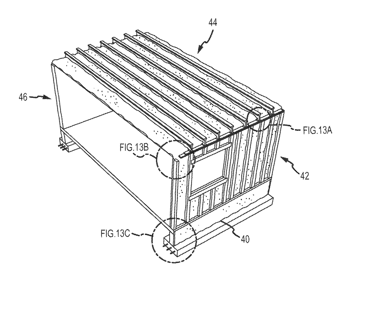
[0035]There is disclosed hereafter a method for erecting a structure, and a construction unit erected thereby. Initial steps of erection may be similar to known techniques, including for example the provision of foundation components such as reinforced poured concrete footings and / or stem walls. The method and structure of the inventive method also may be practiced upon conventional concrete masonry unit (CMU) substructures. Conventional subflooring may be installed generally according to known techniques, including the pouring of concrete slab-on-grade, and / or the installation of truss-supported subflooring upon supporting substructure. The present invention exploits and then improves upon basic processes borrowed from light framing construction.

[0036]As used herein, certain terms have the following definitions:

[0037]A “stud” is a metal or wood post used in the framework of a structure for supporting interior wall panels such as wallboard or similar material. A stud also provides s...


PUM


Abstract

A building construction unit and a method of constructing a building using wall and ceiling panel assemblies that are made up of traditional framing materials, such as studs and interior walls, coated with insulating foam, except that the typical exterior sheathing is optional. Because the panel assembly is structurally sound and thermally insulated, the only reason to install an exterior sheath or additional roofing material is for aesthetic or practical purposes.

Description

BACKGROUND OF THE INVENTION[0001]Field of the Invention[0002]The present invention relates to building construction methods, particularly to a method and unit that provides energy efficiency and structural soundness in buildings through a foam layer shell application.[0003]Background Art[0004]“Light framing” construction is a known construction mode using many small and generally closely spaced members that are assembled by nailing / screwing, and the mode includes balloon, platform and light-steel framing. Light framing building techniques are commonly used, especially in the USA, to erect residential, small commercial or light industrial structures. Light-frame construction using standardized dimensional lumber has become the prevailing light construction method in North America. Use of relatively minimal structural material allows builders to enclose a large area with minimal cost, while achieving a wide variety of architectural styles.[0005]In light platform framing, each floor is...

Claims


Application Information

Patent Timeline
IPC IPC(8): E04B1/00E04B1/76E04B1/18E04B2/56
CPCE04B1/7654E04B1/18E04B1/7604E04B2/562E04B2001/7679E04B1/34815E04B2/58E04B2/707
Inventor LEPAGE, ROBERT
Owner LEPAGE ROBERT
Why Eureka
Try Eureka