
Solder bump array probe tip structure for laser cleaning

a laser cleaning and array probe technology, applied in the direction of electronic circuit testing, measurement devices, instruments, etc., can solve the problems of inability to make the array of probe tips perfectly planar, inconvenient cleaning, and inconvenient cleaning, so as to improve the efficiency and completeness of laser cleaning, and reduce the accumulation rate of sn particles

Active Publication Date: 2017-12-05
INT BUSINESS MASCH CORP
View PDF23 Cites 0 Cited by
  • Summary
  • Abstract
  • Description
  • Claims
  • Application Information

AI Technical Summary

Benefits of technology

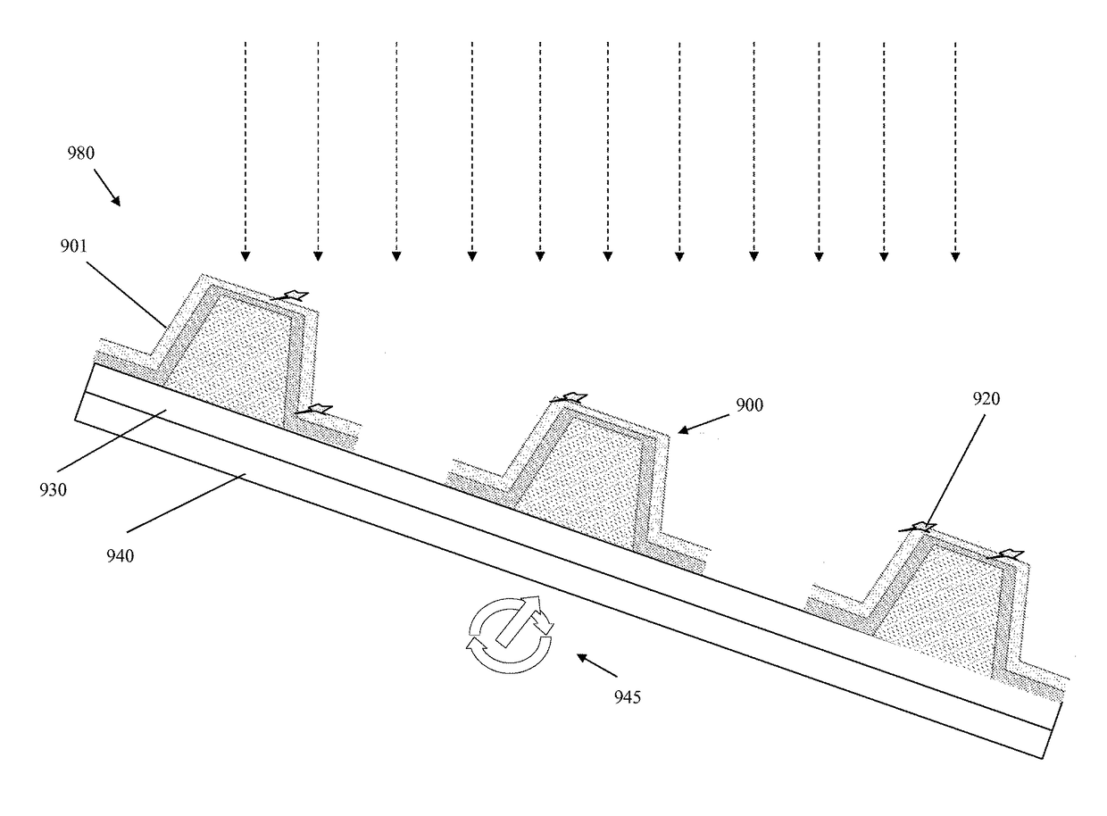
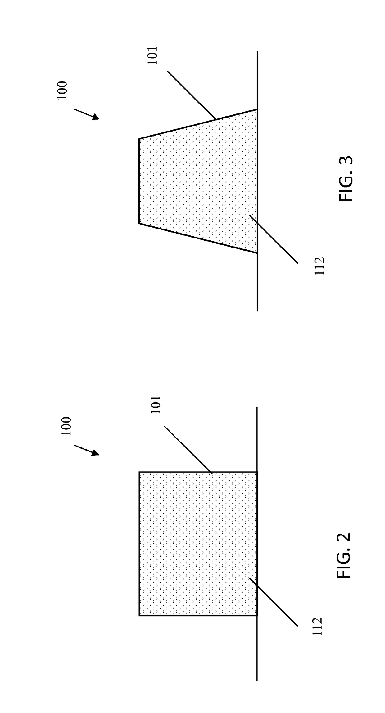
[0007]Various embodiments include a probe tip structure that decreases the accumulation rate of Sn particles to the probe tip structure and enable considerably more efficient and complete laser cleaning.

Problems solved by technology

An array of probe tips cannot be made to be perfectly planar and parallel to the solder bumps on the device to be tested.
However, compliant probes take up too much space due to their spring structure.
Additionally, compliant probes are more expensive and complex, and also have limited current carrying capability.
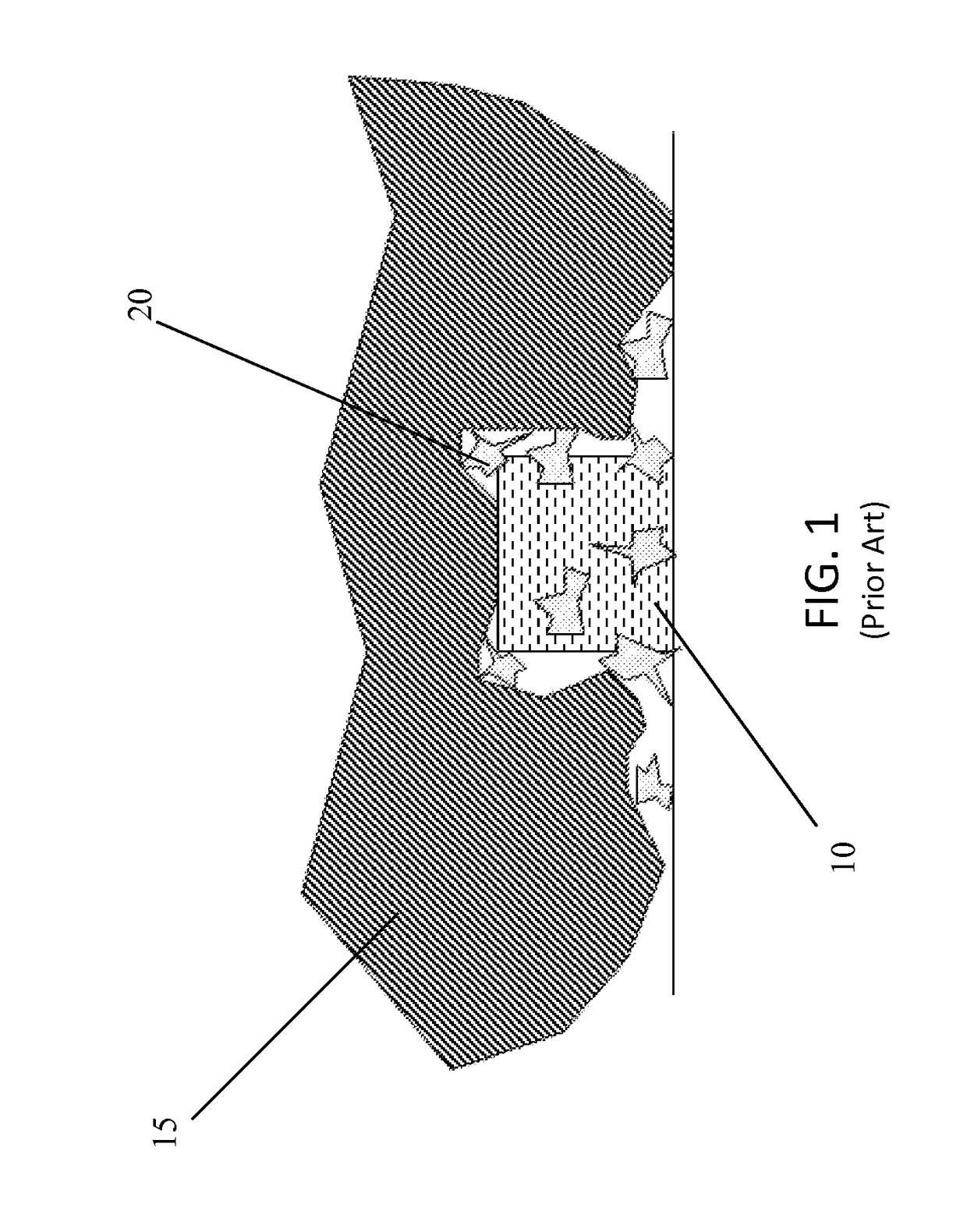
Referring back to FIG. 1, a problem with probe tips 10 of the present state of art is that after testing several wafers, the contact resistance begins to rise, eventually obscuring some of the desired test results.
Unfortunately, this procedure is lengthy and can damage probe tip 10 or other parts of the assembly such as the substrate.
The process also uses dangerous chemicals.
However, the results of the laser cleaning process are not as good as the chemical clean.

Method used


Image

  • Solder bump array probe tip structure for laser cleaning
  • Solder bump array probe tip structure for laser cleaning
  • Solder bump array probe tip structure for laser cleaning

Examples


Embodiment Construction

[0024]As indicated above, the subject matter disclosed herein relates to integrated circuit (IC) devices. More particularly, the subject matter disclosed herein relates to a probe tip structure for testing an array of solder bumps of an integrated circuit and for testing an integrated circuit.

[0025]In the following description, reference is made to the accompanying drawings that form a part thereof, and in which is shown by way of illustration specific exemplary embodiments in which the present teachings may be practiced. These embodiments are described in sufficient detail to enable those skilled in the art to practice the present teachings and it is to be understood that other embodiments may be utilized and that changes may be made without departing from the scope of the present teachings. The following description is, therefore, merely exemplary.

[0026]The rigid probe tip structure disclosed herein decreases the accumulation rate of solder particles on the probe tip. Conventional...


PUM


Abstract

A probe tip structure that decreases the accumulation rate of Sn particles to the probe tip and enables considerably more efficient and complete laser cleaning is disclosed. In an embodiment, the probe structure includes an array of probe tips, each probe tip having an inner core; an interfacial layer bonded to the inner core; and an outer layer bonded to the interfacial layer, wherein the outer layer is resistant to adherence of the solder of the ball grid array package.

Description

BACKGROUND OF THE INVENTION[0001]Embodiments of the invention relate generally to integrated circuit (IC) devices. More particularly, the subject matter disclosed herein relates to a probe tip structure for testing an array of solder bumps of an integrated circuit and for testing an integrated circuit.[0002]Testing products with very large arrays of solder bumps require probes that are durable, accurate and reliable. Achieving good (low resistance, repeatable) electrical probe contact with a solder bump requires some degree of penetration of the bump by the probe tip in order to bypass any surface oxide. As shown in FIG. 1, the present state of art is to force rigid cylindrical probe tips 10 deposited on a ceramic or organic substrate (not shown) into the surface of tin (Sn) solder bumps 15. The cylinders are generally formed from copper (Cu) electroplating through a resist mask, after which the resist is stripped, and nickel (Ni) and gold (Au) layers are plated over the Cu.[0003]An...

Claims


Application Information

Patent Timeline
Patent Type & Authority Patents(United States)
IPC IPC(8): G01R3/00G01R1/067G01R1/073G01R31/28
CPCG01R3/00G01R1/06738G01R31/2886G01R1/07342G01R1/07314
Inventor AUDETTE, DAVID M.BRONSON, JR., DENNIS M.COMEAU, JOSEPH K. V.FREGEAU, DUSTIN M.GARDELL, DAVID L.ROY, III, FREDERICK H.SALIMENO, III, JAMES R.SULLIVAN, TIMOTHY D.
Owner INT BUSINESS MASCH CORP
Learn More