
Twin-screw puffing equipment and using method thereof

An extruding equipment and twin-screw technology, applied in the direction of packaging, etc., can solve problems such as inability to disassemble, increase manufacturing costs, and affect material quality, so as to avoid material quality problems, improve mixing efficiency, and avoid material accumulation.

Active Publication Date: 2020-01-24
安徽珠峰生物科技有限公司
View PDF16 Cites 0 Cited by
  • Summary
  • Abstract
  • Description
  • Claims
  • Application Information

AI Technical Summary

Problems solved by technology

[0003] Meshing type and non-meshing type, partial meshing type and full meshing type, co-rotation and counter-rotation are different, and each has its own advantages in actual production. In the prior art, it is impossible to realize the difference between different screws in the same equipment. Position adjustment, for example, if the equipment is meshing, it cannot be disassembled according to the existing part structure to realize it as a non-engaging type. In order to integrate multiple functions, the manufacturing cost needs to be increased
[0004] At the same time, the existing extruder only realizes the mixing of materials through the rotation of the screw inside the barrel, and is finally extruded out of the barrel. The mixing of the screw is limited. When the material is not mixed uniformly, the quality of the overall material will be affected.

Method used


Image

  • Twin-screw puffing equipment and using method thereof
  • Twin-screw puffing equipment and using method thereof
  • Twin-screw puffing equipment and using method thereof

Examples


Embodiment Construction

[0050] The following will clearly and completely describe the technical solutions in the embodiments of the present invention with reference to the accompanying drawings in the embodiments of the present invention. Obviously, the described embodiments are only some, not all, embodiments of the present invention. Based on the embodiments of the present invention, all other embodiments obtained by persons of ordinary skill in the art without creative efforts fall within the protection scope of the present invention.

[0051] In describing the present invention, it is to be understood that the terms "opening", "upper", "lower", "thickness", "top", "middle", "length", "inner", "surrounding" etc. Indicating orientation or positional relationship is only for the convenience of describing the present invention and simplifying the description, and does not indicate or imply that the components or elements referred to must have a specific orientation, be constructed and operated in a sp...


PUM


Abstract

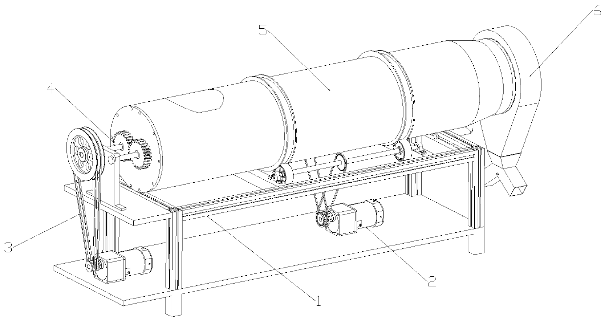
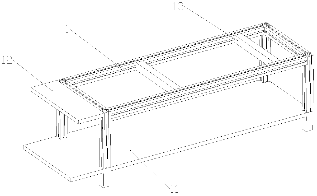
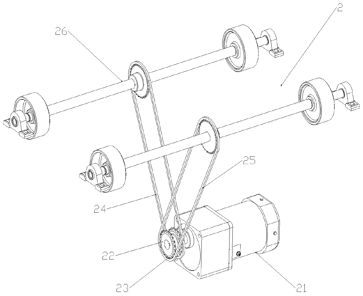
The invention discloses twin-screw puffing equipment and a using method thereof. The twin-screw puffing equipment comprises a workbench, wherein a first driving device is arranged below the workbench,the first driving device comprises a first servo motor fixed on one side of the upper end of a support bottom plate, a second driving device is arranged at one side below the workbench, the second driving device comprises a second servo motor fixed at the upper end of the support bottom plate, a rotating device comprises a first screw fixedly connected with the central position of a belt pulley,and the side edge of the first screw is provided with a second screw. According to the twin-screw structure, the equipment can be changed into meshing type, non-meshing type and partial meshing type by disassembling and assembling according to the existing part structure, so that multiple functions are realized, and the production cost is reduced; meanwhile, the position of a connecting sleeve canbe adjusted, fastening bolts and the two end walls of the connecting sleeve are tightly connected, clamping and fixing of the connecting sleeve are realized, the rotation direction of a propeller canbe reversed, and free adjustment of co-rotation and counter-rotation is achieved.

Description

technical field [0001] The invention relates to the field of twin-screw extruders, in particular to a twin-screw extruder and an application method thereof. Background technique [0002] The twin-screw extruder is one of the multi-screw extruders, which is developed on the basis of the single-screw extruder. In the barrel of the twin-screw extruder, two screws are placed side by side. So it is called twin-screw extruder. According to the relative position of the screw, it can be divided into meshing type and non-engaging type, and the meshing type can be divided into partial meshing type and full meshing type; It can be divided into two types: inward and outward. The nature of the pressure zone of the co-rotating twin-screw is different. The material is rotated by the screw in the inner cavity of the sleeve to produce a high-pressure zone and a low-pressure zone. [0003] Meshing type and non-meshing type, partial meshing type and full meshing type, co-rotation and counte...

Claims


Application Information

Patent Timeline
Patent Type & Authority Applications(China)
IPC IPC(8): B65G33/18B65G33/26B65G33/24B65G33/34
CPCB65G33/18B65G33/24B65G33/26B65G33/34
Inventor 朱林范翠玲王瑞班文杰朱金龙朱峰朱梅郭俊李玉芹朱小梅
Owner 安徽珠峰生物科技有限公司
Learn More