A kind of one-way two-way flywheel and its adjustment system
An adjustment system and flywheel technology, applied in the field of fitness equipment, can solve the problems of human injury, inconvenient fitness cost, inability to make fitness movements, etc., and achieve the effect of convenient adjustment
- Summary
- Abstract
- Description
- Claims
- Application Information
AI Technical Summary
Problems solved by technology
Method used
Image
Examples
Embodiment 1
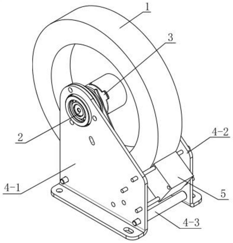
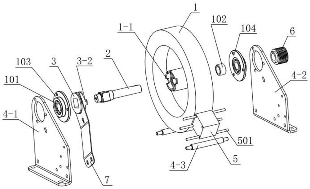
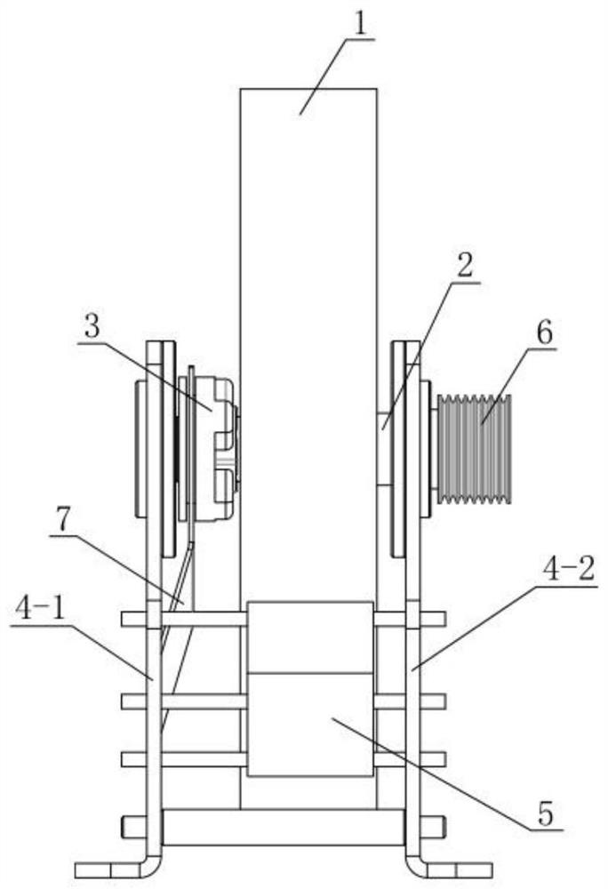
[0047] A one-way two-way flywheel, such as Figure 1-3 As shown, it includes a flywheel body 1, a central shaft 2, a coupling 3 and a supporting mechanism.
[0048] In this example, if figure 2 As shown, the left and right sides of the flywheel body 1 are provided with rolling bearings 101. In this embodiment, the rolling bearings 101 are deep groove ball bearings, but not limited thereto; the axis of the flywheel body 1 is embedded with a one-way bearing 102. The one-way bearing 102 in this embodiment is a one-way needle bearing, but it is not limited thereto.
[0049] The central shaft 2 is installed at the axis of the flywheel body 1 and passed through the rolling bearing 101 and the one-way bearing 102 . Both ends of the central shaft 2 are supported by the supporting mechanism.
[0050] In this embodiment, the support mechanism is composed of a left support plate 4-1 and a right support plate 4-2, and at least two connecting rods are passed between the left support pla...
Embodiment 2
[0058] A unidirectional and bidirectional flywheel adjustment system includes a shifting assembly, a brake assembly and the unidirectional and bidirectional flywheel in Embodiment 1.
[0059] Such as Figure 6-8 As shown, the shifting assembly includes: a spring fork 7 , an adjustment handle 8 , and a shifting cable 9 .
[0060] In this example, if Figure 7 and 8 As shown, the spring fork 7 is arranged on the shaft coupling 3 for moving the shaft coupling 3 . Such as Figure 4 As shown, the outer wall of the coupling 3 is provided with an annular slot 3-3, and the top end of the spring fork 7 is concavely provided with a U-shaped groove 7-1, and the arc of the U-shaped groove 7-1 is in line with The radians of the annular locking groove 3-3 match, so that the spring shift fork 7 can be clamped in the annular locking groove 3-3 through the U-shaped groove 7-1, as image 3 As shown, the bottom of the spring fork 7 is fixed to the left support plate 4-1 by bolts.
[0061] ...
Embodiment 3
[0075] This embodiment provides a single-direction flywheel adjustment system. The difference from Embodiment 2 is that the adjustment of the shift assembly and the brake assembly are set separately in this embodiment.
[0076] Specifically, the brake line is directly connected to the fixed seat 10-2, and the end of the brake line away from the brake pad 10 is connected to the brake handle, and the brake pad 10 is driven to rotate through the brake handle. At this time, the shift cable 9 can Set to a straight line, the tail end of the shifting cable 9 is connected to the adjustment handle 8, and the front end is connected to the spring fork 7, and the single and bi-directional mode of the flywheel is adjusted through the adjustment handle 8.
PUM
 Abstract
Description
Claims
Application Information
 - R&D
- Intellectual Property
- Life Sciences
- Materials
- Tech Scout
- Unparalleled Data Quality
- Higher Quality Content
- 60% Fewer Hallucinations
Browse by: Latest US Patents, China's latest patents, Technical Efficacy Thesaurus, Application Domain, Technology Topic, Popular Technical Reports.
© 2025 PatSnap. All rights reserved.Legal|Privacy policy|Modern Slavery Act Transparency Statement|Sitemap|About US| Contact US: help@patsnap.com


