
Automatic mechanical device for recycling metal machining excess materials

A mechanical device and metal processing technology, which is applied in the direction of metal processing machinery parts, metal processing equipment, manipulators, etc., can solve the problems of high purchase cost, high labor separation intensity, and heavy burden, and achieve the effect of high flexibility

Active Publication Date: 2020-11-06
青岛正大正电力环保设备有限公司
View PDF5 Cites 0 Cited by
  • Summary
  • Abstract
  • Description
  • Claims
  • Application Information

AI Technical Summary

Problems solved by technology

[0002] A large amount of machining residues and chips are often produced in metal processing, such as cutting and pressure processing. After the processing is completed, the processing residues and chips are discharged from the machine tool. Operators need to separate the residues and chips before collecting them. In a processing workshop, these surplus materials may be collected in one place and then sorted. The manual separation is too strong, and the purchase cost of equipment is relatively high if the sorting is done through a mechanical structure. For small processing plants, it is a burden bigger

Method used


Image

  • Automatic mechanical device for recycling metal machining excess materials
  • Automatic mechanical device for recycling metal machining excess materials
  • Automatic mechanical device for recycling metal machining excess materials

Examples


Embodiment Construction

[0020] In order to make the purpose, technical solutions and advantages of the embodiments of the present invention clearer, the technical solutions in the embodiments of the present invention will be clearly and completely described below in conjunction with the drawings in the embodiments of the present invention. Obviously, the described embodiments It is a part of embodiments of the present invention, but not all embodiments. Based on the embodiments of the present invention, all other embodiments obtained by persons of ordinary skill in the art without creative efforts fall within the protection scope of the present invention.

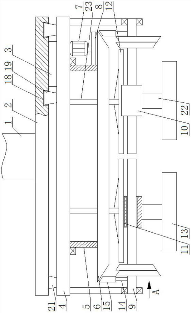
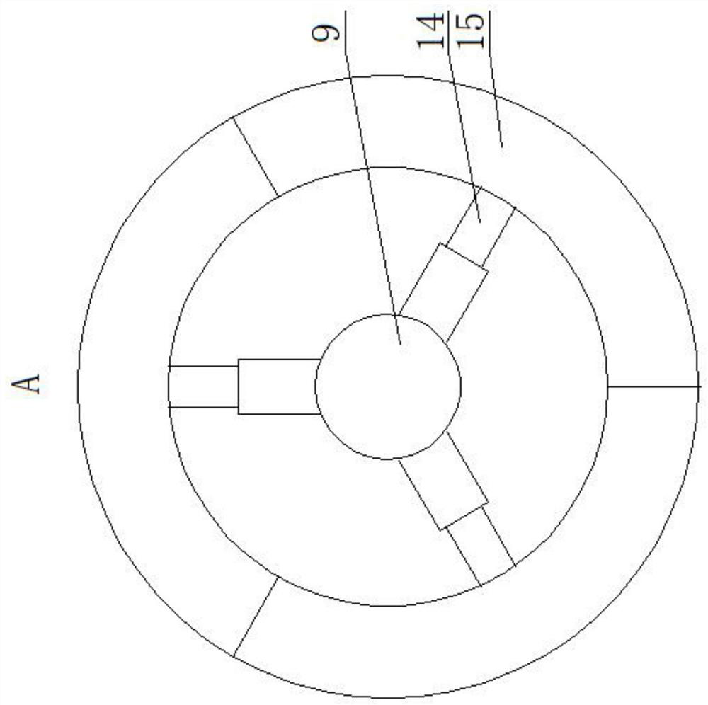
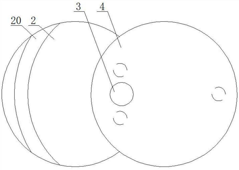
[0021] An automatic mechanical device for recovering metal processing surplus material, as shown in the figure, includes a fixed column 1, the upper end of which is fixedly installed in the workshop. The fixed column 1 can be a telescopic structure to adjust the height of the device. Fixedly connected to the top surface of the substrate 2, it is c...


PUM


Abstract

The invention relates to an automatic mechanical device for recycling metal machining excess materials. The automatic mechanical device comprises a fixing column, the lower end of the fixing column isfixedly connected with the top face of a base plate, the eccentric position of the bottom face of the base plate is connected with the top face of a bearing plate through a rotating shaft, a power device acting on the rotating shaft is arranged on the bottom face of the base plate, the bottom face of the bearing plate is connected with the upper end of a sleeve through a bearing, a bevel gear isfixedly installed at the lower end of the sleeve, a motor is fixedly installed on the bottom face of the bearing plate, the output end of the motor faces downwards and is fixedly provided with a gear,a tooth groove meshed with the gear is formed in the periphery of the sleeve, a plurality of screws are arranged below the bevel gear, the screws are connected with the bearing plate through bearingpedestals, a swivel nut is installed on the periphery of each screw in a threaded mode, a limiting groove is formed in the top of each swivel nut, a fan-shaped block is arranged on the bottom of eachswivel nut, and an electromagnet connected with a power circuit is arranged on the bottom of each fan-shaped block. The device can be used for recycling the excess materials on a magnetic metal machining site in real time, can also be used for roughly classifying the magnetic metal excess materials after the magnetic metal excess materials are gathered, and can also be used for grabbing and movingmagnetic metal.

Description

technical field [0001] The invention belongs to the field of metal processing, in particular to an automatic mechanical device for recycling metal processing surplus materials. Background technique [0002] A large amount of machining residues and chips are often produced in metal processing, such as cutting and pressure processing. After the processing is completed, the processing residues and chips are discharged from the machine tool. Operators need to separate the residues and chips before collecting them. In a processing workshop, these surplus materials may be collected in one place and then sorted. The manual separation is too strong, and the purchase cost of equipment is relatively high if the sorting is done through a mechanical structure. For small processing plants, it is a burden larger. Contents of the invention [0003] The invention provides an automatic mechanical device for recycling metal processing surplus materials, which is used to solve the defects i...

Claims


Application Information

Patent Timeline
Patent Type & Authority Applications(China)
IPC IPC(8): B23Q11/00B25J11/00B25J15/06
CPCB23Q11/0064B25J11/005B25J15/0608
Inventor 康剑莉
Owner 青岛正大正电力环保设备有限公司
Learn More