
A Thin-Wall Pipe Circular Cutting Mechanism Applicable to Different Wall Thickness

A thin-walled pipe and ring cutting technology, which is applied in the direction of pipe shearing device, shearing device, shearing machine accessory device, etc., can solve the problems of incomplete cutting, high cost, waste of raw materials, etc., and achieve reduced investment and wide applicability Effect

Active Publication Date: 2020-08-04
徐州市瑞泰钢管有限公司
View PDF8 Cites 0 Cited by
  • Summary
  • Abstract
  • Description
  • Claims
  • Application Information

AI Technical Summary

Problems solved by technology

[0002] Thin-walled pipes mostly refer to steel pipes with a wall thickness of 0.3-0.6mm. The ports of such steel pipes are easy to wear during processing, and it is necessary to cut the worn parts of the ports before leaving the warehouse. In the traditional technology, the cutting blade is usually set at the thin On the outside of the wall tube, the thin-walled tube rotates during the cutting process, and the cutting blade squeezes and cuts the thin-walled tube. However, due to the small force-bearing area of ​​this cutting method, the cutting process concentrates the extrusion force on the thin-walled tube. In one point, because the thin-walled tube is thin, and the wall thickness of the thin-walled tube of different specifications is different, during the cutting process, the thin-walled tube is often dented under extrusion, resulting in incomplete cutting, which needs to be repaired again before it can be used, resulting in It reduces the waste of raw materials, and the cutting method of driving the thin-walled steel pipe to rotate can only be applied to thin-walled pipes with smaller diameters. For thin-walled pipes with larger diameters, large-scale rotary equipment is required to drive the thin-walled pipes to rotate, and the cost is high.

Method used


Image

  • A Thin-Wall Pipe Circular Cutting Mechanism Applicable to Different Wall Thickness
  • A Thin-Wall Pipe Circular Cutting Mechanism Applicable to Different Wall Thickness
  • A Thin-Wall Pipe Circular Cutting Mechanism Applicable to Different Wall Thickness

Examples


Embodiment Construction

[0023] The following will clearly and completely describe the technical solutions in the embodiments of the present invention with reference to the accompanying drawings in the embodiments of the present invention. Obviously, the described embodiments are only some, not all, embodiments of the present invention.

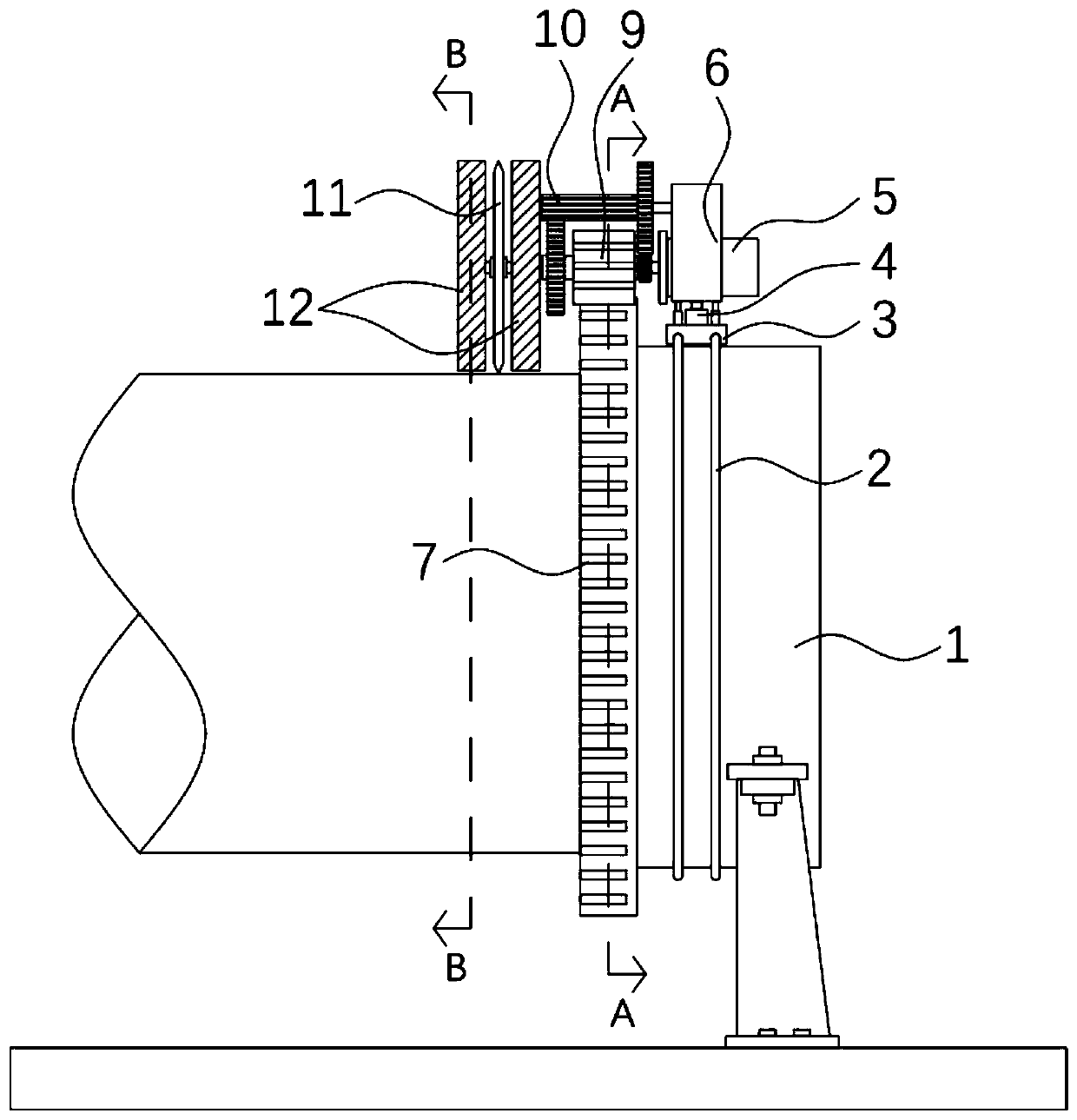
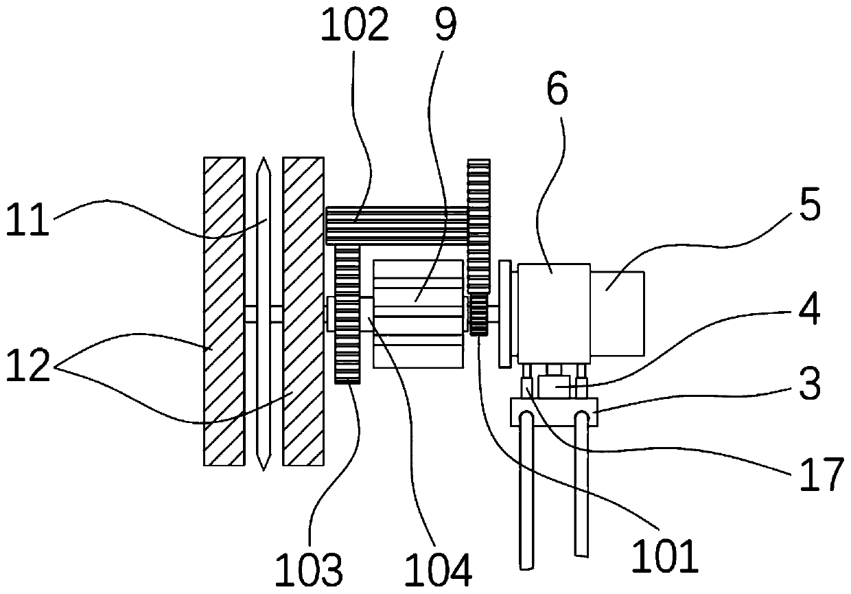
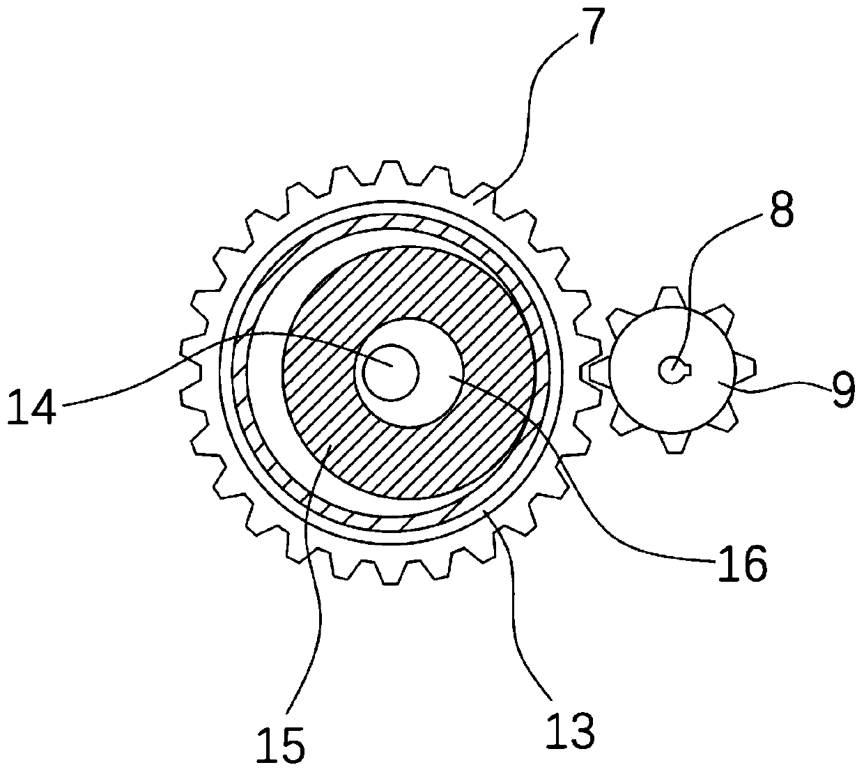
[0024] refer to Figures 1 to 6 , a thin-walled pipe circumcision mechanism suitable for different wall thicknesses, comprising a circular fixing frame 1, the outer surface of the circular fixing frame 1 is fixedly connected with an outer tooth circle 7, and the outer surface of the circular fixing frame 1 is also fixedly connected with The ring slide rail 2 is slidably connected with a slider 3 on the ring slide rail 2, and a telescopic mechanism 4 is installed on the slider 3. The telescopic mechanism 4 can adopt common products with telescopic functions such as cylinders on the market. The output end of the telescopic mechanism 4 A fixed frame 6 is fixedly connect...


PUM


Abstract

The invention discloses a thin-walled pipe ring cutting mechanism suitable for different wall thicknesses. The ring cutting mechanism comprises a round fixed frame. An outer tooth ring is fixedly connected with the outer surface of the round fixed frame. An annular slide rail is fixedly connected with the outer surface of the round fixed frame. A slider is slidingly connected to the annular sliderail. A telescopic mechanism is installed on the slider. The output end of the telescopic mechanism is fixedly connected with a fixed frame. A motor is fixedly connected with the fixed frame. By arranging a multi-stage speed reduction mechanism, the meshing of the outer tooth ring and a planet gear is realized, the circumferential movement of a cutting plate can be driven during cutting, the ringcutting mechanism is suitable for large-aperture thin-walled pipes, and the defect that large-aperture thin-walled pipes need large rotating devices in a traditional technology is effectively overcome. Through the internal and external matching of a cushion block stop piece and a cushion block, the two-point type fixing of the two sides of the cutting plate is realized, it is avoided that the thin-walled pipes are indented under the effect of extrusion force during cutting and cutting is not completed.

Description

technical field [0001] The invention relates to the technical field of cutting thin-walled steel pipes, in particular to a ring-cutting mechanism for thin-walled pipes with different wall thicknesses. Background technique [0002] Thin-walled pipes mostly refer to steel pipes with a wall thickness of 0.3-0.6mm. The ports of such steel pipes are easily worn during processing, and it is necessary to cut the worn parts of the ports before leaving the warehouse. In the traditional technology, the cutting blade is usually set at the thin On the outside of the wall tube, the thin-walled tube rotates during the cutting process, and the cutting blade squeezes and cuts the thin-walled tube. However, due to the small force-bearing area of ​​this cutting method, the cutting process concentrates the extrusion force on the thin-walled tube. In one point, because the thin-walled tube is thin, and the wall thickness of the thin-walled tube of different specifications is different, during t...

Claims


Application Information

Patent Timeline
Patent Type & Authority Patents(China)
IPC IPC(8): B23D21/00B23D33/02
CPCB23D21/00B23D33/02
Inventor 夏静
Owner 徐州市瑞泰钢管有限公司
Learn More