
Methods and devices for optical aberration correction

a technology of optical aberration and correction method, applied in the field of near-eye systems, can solve the problems of increasing cost and power consumption, requiring faster electronics, and introducing distortions and chromatic aberrations into the projected imag

Active Publication Date: 2017-12-05
ESIGHT CORP
View PDF4 Cites 11 Cited by
  • Summary
  • Abstract
  • Description
  • Claims
  • Application Information

AI Technical Summary

Problems solved by technology

However, such near-to-eye displays employ a number of optical elements including the displays, intermediate lens and prisms, and the user's pupils even without consideration of whether they use prescription refractive correction lenses.
As such the optical train from display to pupil within near-to-eye displays introduces distortions and chromatic aberrations into the projected image.
In many instances the correction of these distortions and chromatic aberrations requires either the design of the optical train to become significantly more complex through additional corrective elements adding to weight, cost, and size; require complex image processing thereby adding to latency from image acquisition to presentation which has severe impacts after a relatively low latency threshold is exceeded thereby requiring faster electronics with increased cost and power consumption; or a tradeoff in the performance of the near-to-eye display must be made.

Method used


Image

  • Methods and devices for optical aberration correction
  • Methods and devices for optical aberration correction
  • Methods and devices for optical aberration correction

Examples


Embodiment Construction

[0057]The present invention is directed to near-to-eye systems and more particularly to methods and devices for addressing optical aberrations within such near-to-eye systems and near-to-eye vision augmentation systems.

[0058]The ensuing description provides exemplary embodiment(s) only, and is not intended to limit the scope, applicability or configuration of the disclosure. Rather, the ensuing description of the exemplary embodiment(s) will provide those skilled in the art with an enabling description for implementing an exemplary embodiment. It being understood that various changes may be made in the function and arrangement of elements without departing from the spirit and scope as set forth in the appended claims.

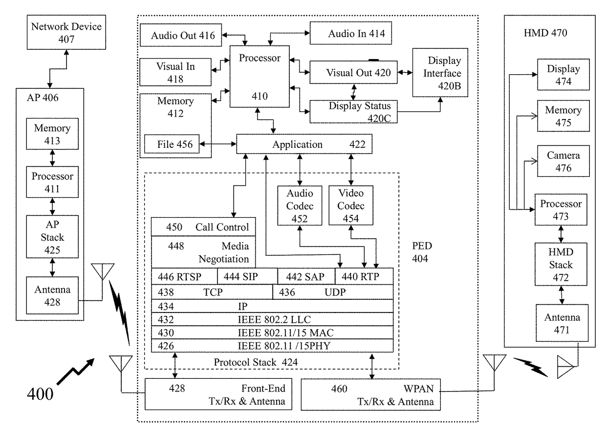
[0059]A “portable electronic device” (PED) as used herein and throughout this disclosure, refers to a wireless device used for communications and other applications that requires a battery or other independent form of energy for power. This includes devices, but is not ...


PUM


Abstract

Near-to-eye displays within head mounted devices offer both users with and without visual impairments enhanced visual experiences either by improving or augmenting their visual perception. Unless the user directly views the display without intermediate optical elements then the designer must consider chromatic as well as other aberrations. Within the prior art the optical train is either complex through additional corrective elements adding to weight, cost, and size or through image processing. However, real time applications with mobile users require low latency to avoid physical side effects. Accordingly, it would be beneficial to provide near-to-eye displays mitigating these distortions and chromatic aberrations through pre-distortion based electronic processing techniques in conjunction with design optimization of the optical train with low weight, low volume, low complexity, and low cost. Further, it would be beneficial to exploit consumer grade low cost graphics processing units rather than application specific circuits.

Description

CROSS-REFERENCE TO RELATED APPLICATIONS[0001]This patent application claims the benefit of priority from U.S. Provisional Patent Application 62 / 150,911 filed Apr. 22, 2015 entitled “Methods and Devices for Optical Aberration Correction”, the entire contents of which are incorporated herein by reference.FIELD OF THE INVENTION[0002]This invention relates to near-to-eye systems and more particularly to methods and devices for addressing optical aberrations within such near-to-eye systems and near-to-eye vision augmentation systems.BACKGROUND OF THE INVENTION[0003]A near-to-eye (or near-eye) display is a wearable device that creates a display in front of the user's field of vision. The display may be transparent or opaque, depending on the application. For example, a transparent display can overlay information and graphics on top on the real world, while an opaque display can provide an immersive theater-like experience.[0004]Near-to-eye Displays can be broadly placed in two categories,...

Claims


Application Information

Patent Timeline
Patent Type & Authority Patents(United States)
IPC IPC(8): G06T5/00G02B13/00G06T3/00G06T15/04G06T15/20G02B27/01G02B17/08G02C7/08
CPCG06T5/006G02B17/086G02B27/017G02B27/0172G06T3/0093G06T15/04G06T15/20G02B13/007G06T2215/16G02B2027/011G02B2027/014G02B2027/0116G02B2027/0178G02C7/086G02C2202/10G02C2202/22G09G3/20G09G2320/0666
Inventor JONES, FRANKERSHADI, MEHDI AREZOOMANDBACQUE, JAMES BENSON
Owner ESIGHT CORP
Learn More