System and method of detecting malicious content

a technology of malicious content and detection system, applied in computing, instruments, electric digital data processing, etc., can solve the problems of increasing complexity and sophistication of modern computer worms, difficult to detect computer worms, and difficult to distinguish between ordinary communications traffic and computer worms

Active Publication Date: 2017-12-05
FIREEYE SECURITY HLDG US LLC
View PDF490 Cites 145 Cited by
  • Summary
  • Abstract
  • Description
  • Claims
  • Application Information

AI Technical Summary

Benefits of technology

The patent describes a system that detects and blocks computer worms in a communication network. The system can identify worms by analyzing network communications or by creating simulated worms to mimic their behavior. The system is designed to protect the network in real-time, preventing the worms from spreading further.

Problems solved by technology

Detecting and distinguishing computer worms from ordinary communications traffic within a computer network is a challenging problem.
Moreover, modern computer worms operate at an ever increasing level of sophistication and complexity.
Consequently, it has become increasingly difficult to detect computer worms.
Misuse detection works reliably for known attack patterns but is not particularly useful for detecting novel attacks.
The difficulty inherent in this approach is that universal definitions of normal behavior are difficult to obtain.
This computer worm containment system, however, does not have a mechanism for repair and recovery of infected computer networks.
While this approach may be successful in some circumstances, this approach is limited in other circumstances.
Firstly, it is possible for a network packet to be fully compatible with published protocol standard specifications and still trigger a buffer overflow type of software error due to the presence of a software bug.
Secondly, not all protocols of interest can be checked for standards compliance because proprietary or undocumented protocols may be used in a computer network.
Moreover, evolutions of existing protocols and the introduction of new protocols may lead to high false positive rates of computer worm detection when “good” behavior cannot be properly and completely distinguished from “bad” behavior.
Encrypted communications channels further complicate protocol checking because protocol compliance cannot be easily validated at the network level for encrypted traffic.
One problem with this approach is that probe attempts do not necessarily indicate the presence of a computer worm because there may be legitimate reasons for probing a computer network.
Another problem with this approach is that a conventional honey farm does not detect passive computer worms and does not extract signatures or transport vectors in the face of chaff emitting computer worms.
Although this approach may work for well known computer worms that periodically recur, such as the CodeRed computer worm, this approach does not work for novel computer worm attacks exploiting a zero-day vulnerability (e.g., a vulnerability that is not widely known).
In addition to false positive related problems, the computer worm containment system does not distinguish between the actual transport vector of a computer worm and a transport vector including a spuriously emitted chaff trail.
As a result, simply examining malicious traffic to determine the transport vector can lead to a broad denial of service (DOS) attack on the computer network.
Further, the computer worm containment system does not determine a signature of the computer worm that can be used to implement content filtering of the computer worm.
In addition, the computer worm containment system does not have the ability to detect stealthy passive computer worms, which by their very nature cause no anomalous communication patterns.

Method used


Image

  • System and method of detecting malicious content
  • System and method of detecting malicious content
  • System and method of detecting malicious content

Examples


Embodiment Construction

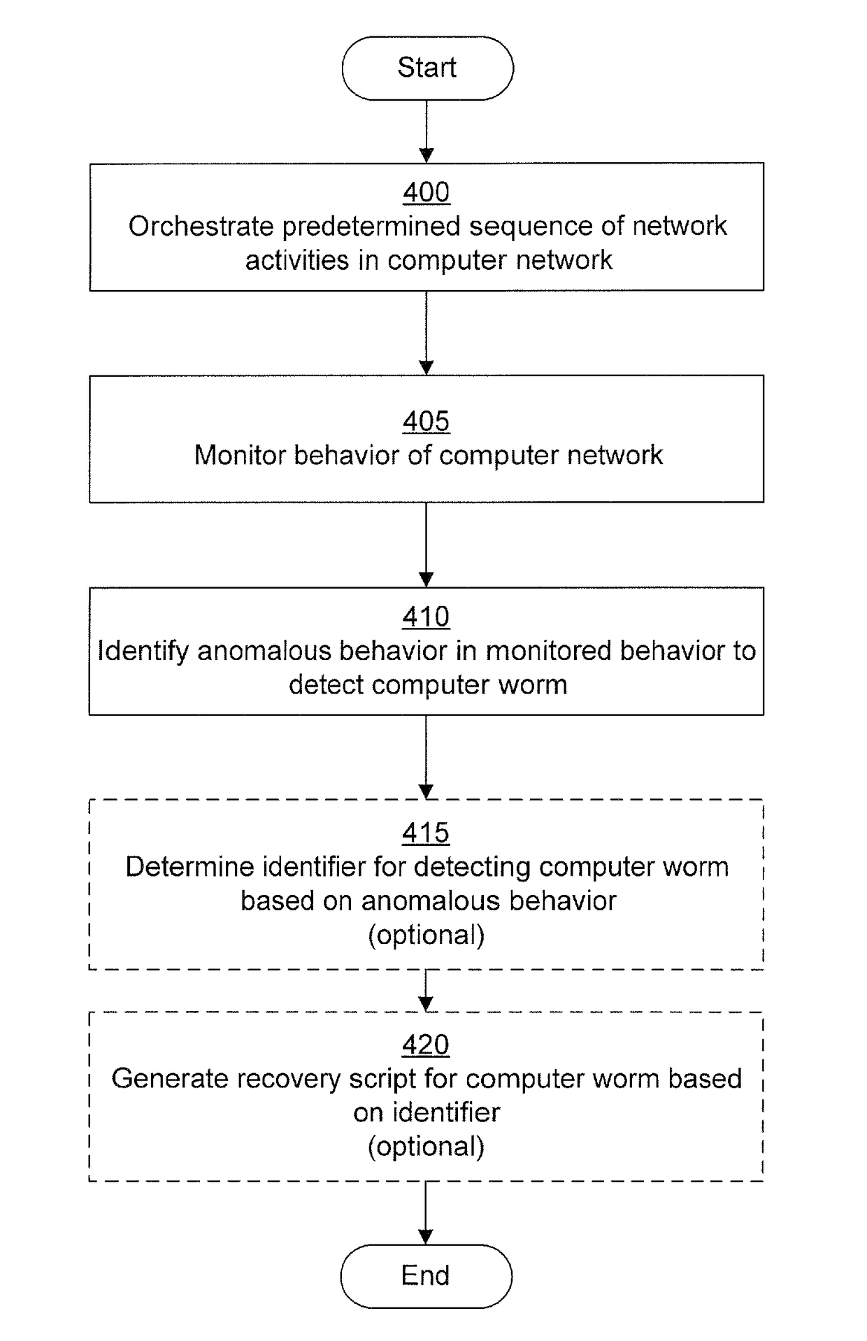
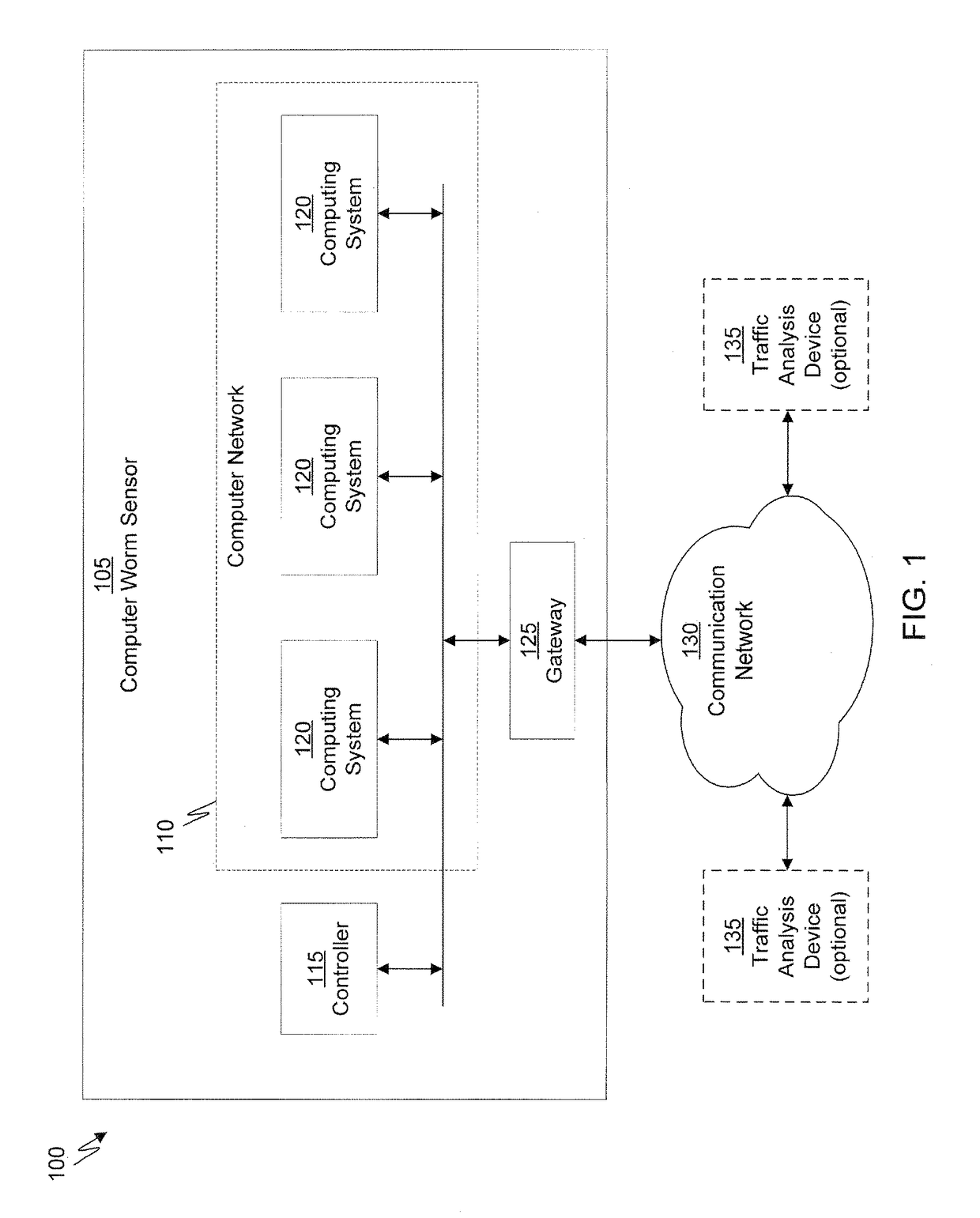
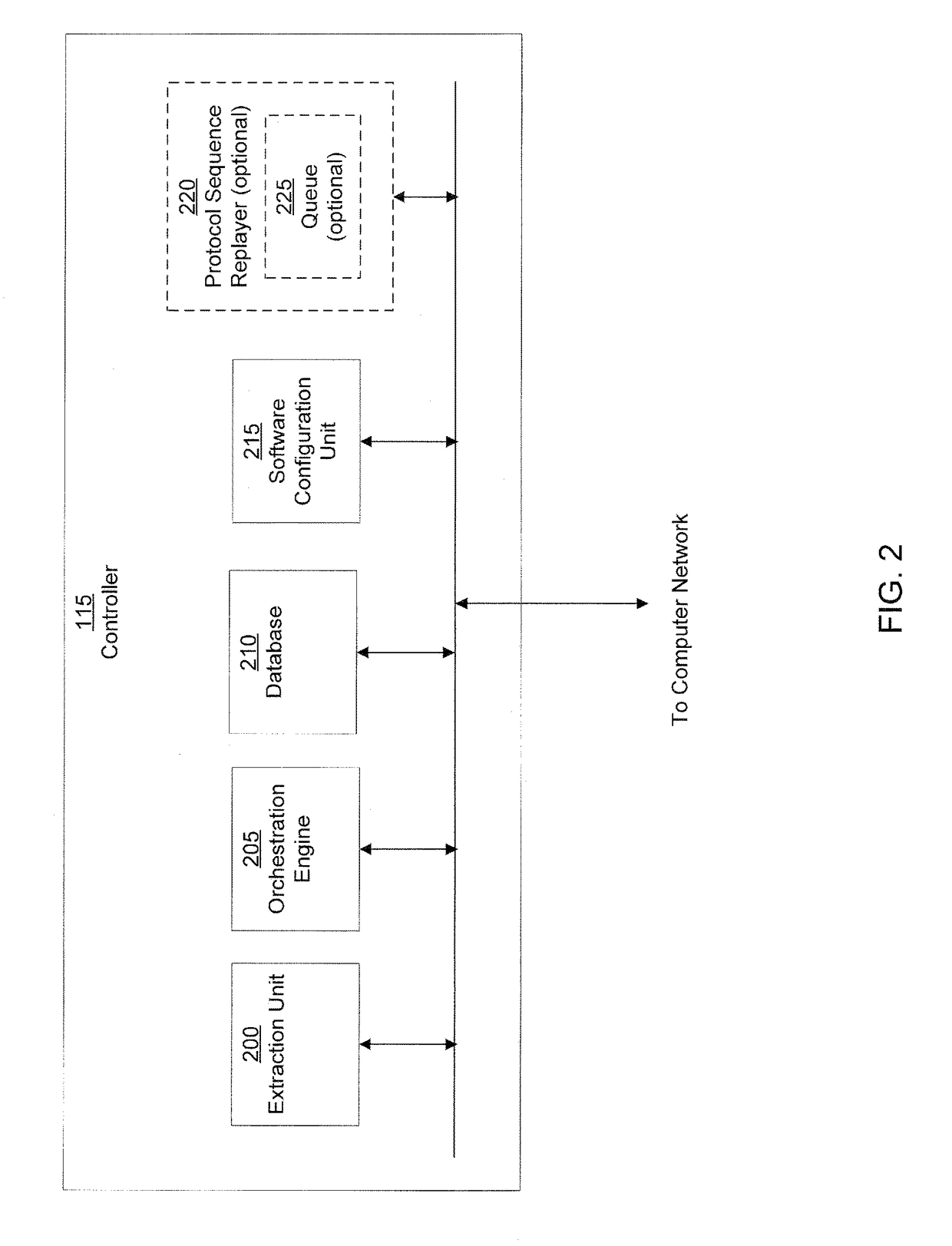
[0024]A computer worm containment system in accordance with one embodiment of the present invention detects and blocks computer worms. Detection can be accomplished through the use of a computer worm detection system that employs a decoy computer network having orchestrated network activities. The computer worm detection system is configured to permit computer worms to infect the decoy computer network. Alternately, rather than infect the decoy network, communications that are characteristic of a computer worm can be filtered from communication traffic and replayed in the decoy network. Detection is then based on the monitored behavior of the decoy computer network. Once a computer worm has been detected, an identifier of the computer worm is determined and provided to a computer worm blocking system that is configured to protect one or more computer systems of a real computer network. In some embodiments, the computer worm detection system can generate a recovery script to disable ...


PUM


Abstract

A computer worm containment system comprises a detection system and a blocking system. The detection system orchestrates a sequence of network activities in a decoy computer network and monitors that network to identify anomalous behavior and determine whether the anomalous behavior is caused by a computer worm. The detection system can then determine an identifier of the computer worm based on the anomalous behavior. The detection system can also generate a recovery script for disabling the computer worm or repairing damage caused by the computer worm. The blocking system is configured to use the computer worm identifier to protect another computer network. The blocking system can also use the recovery script to disable a computer worm within the other network and to repair damage caused to the network by the worm.

Description

CROSS-REFERENCE TO RELATED APPLICATIONS[0001]This application is a continuation of U.S. patent application Ser. No. 11 / 151,812, filed Jun. 13, 2005, which claims the benefit of U.S. provisional patent application No. 60 / 579,953, filed Jun. 14, 2004 and entitled “System and Method of Detecting Computer Worms,” which is incorporated by reference herein. This application is related to U.S. patent application Ser. No. 11 / 096,287, filed Mar. 31, 2005 and entitled “System and Method of Detecting Computer Worms,” now U.S. Pat. No. 8,528,086.BACKGROUND[0002]Field of the Invention[0003]The present invention relates generally to computing systems, and more particularly to systems and methods of detecting and blocking computer worms in computer networks.[0004]Background Art[0005]Detecting and distinguishing computer worms from ordinary communications traffic within a computer network is a challenging problem. Moreover, modern computer worms operate at an ever increasing level of sophistication...

Claims


Application Information

Patent Timeline
Patent Type & Authority Patents(United States)
IPC IPC(8): G06F21/56H04L29/06G06F21/55
CPCH04L63/145H04L63/1433H04L63/1491H04L63/1408G06F21/56G06F21/554G06F21/568
Inventor AZIZ, ASHAR
Owner FIREEYE SECURITY HLDG US LLC
Why Eureka
Try Eureka