Developing device having rotating feeding member

a technology of developing device and feeding member, which is applied in the direction of electrographic process apparatus, instruments, optics, etc., can solve the problems of unstable developer amount in the developing container, inability to stabilize enough, and irregular developer amount discharged through the discharge opening, etc., to achieve the effect of lowering the flowability of developer and not easily discharged unstably

Active Publication Date: 2017-12-12
CANON KK
View PDF17 Cites 1 Cited by
  • Summary
  • Abstract
  • Description
  • Claims
  • Application Information

AI Technical Summary

Benefits of technology

[0010]A principal object of the present invention is to provide a developing device having a constitution in which a blade portion at a discharge opening opposing portion is decreased in diameter, wherein raising of a developer fed along a discharge opening is suppressed and is not readily discharged unstably even when flowability of the developer is lowered.

Problems solved by technology

Further, the discharged amount is influenced by the flowability of the developer and therefore even in the constitution of JP-A 2007-264511, the developer amount in the developing container has been unable to be stabilized sufficiently.
However, as pointed out in JP-A 2007-264511, when the flowability of the developer is lowered by an increase in temperature and humidity or by acceleration of a deterioration of the developer, the amount of the developer discharged through the discharge opening starts to fluctuate irregularly.
When the flowability of the developer is lowered, a so-called angle of repose becomes large, so that the raised developer is not readily collapsed by its own weight.

Method used


Image

  • Developing device having rotating feeding member
  • Developing device having rotating feeding member
  • Developing device having rotating feeding member

Examples


embodiment 1

[0090]FIG. 8A is an illustration of a first feeding screw in Embodiment 1. FIG. 8B is an enlarged top view of a rib portion in FIG. 8A. FIG. 8C is an enlarged front view of the rib portion in FIG. 8A. FIG. 9 is an illustration of a length of ribs. Parts (a) and (b) of FIG. 10 are graphs showing an effect of the ribs in the first feeding screw in Embodiment 1 ((a)) relative to ribs in a Comparative Embodiment 3 ((b)).

[0091]As shown in FIG. 8A, the developer discharge opening 40 as an example of the discharge opening is provided in the side wall of the developing chamber 23 at the side upstream of the developing sleeve 28 with respect to the developer feeding direction and through which a part of the developer circulated in the developing container 22 overflows and discharges. The hopper 31 as an example of the carrier supplying means supplies the toner and the carrier to the developing chamber 23 at the side downstream of the developer discharge opening 40 with respect to the develop...

embodiment 2

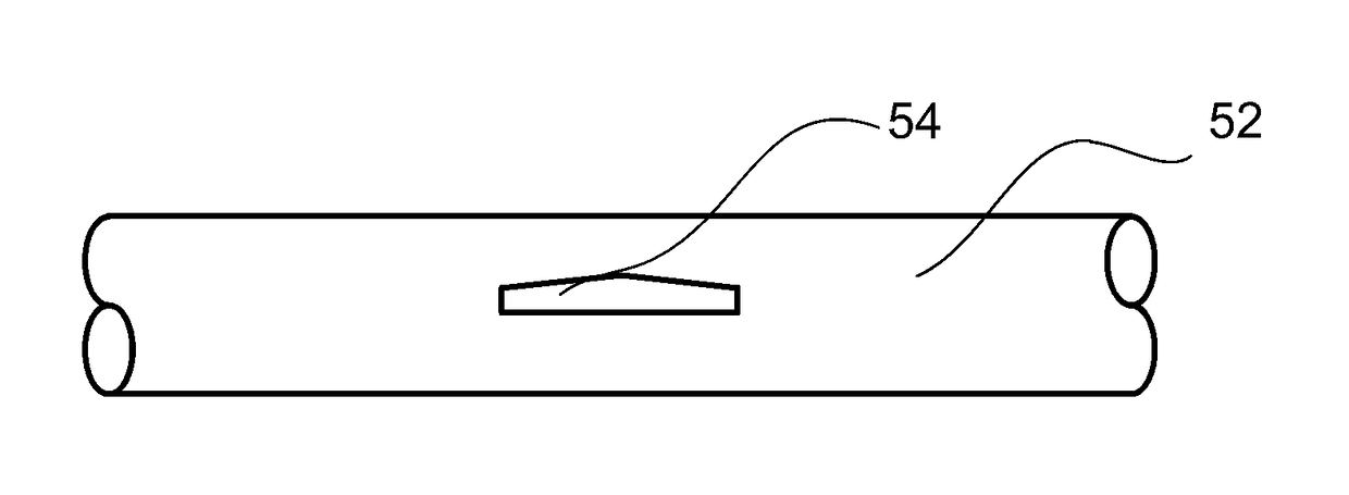
[0121]FIG. 11A is an illustrations of a structure of a first feeding screw in Embodiment 2. FIG. 8B is an enlarged view of a rib 54 in FIG. 11A. FIG. 11C is an enlarged top view of the rib portion in FIG. 11A. FIG. 11D is an enlarged front view of a rib portion in FIG. 11A. Parts (a) to (d) of FIG. 12 are graphs each showing a relationship between an inclination angle of an inclined surface of a rib and a discharging / stirring performance. In Embodiment 2, different from Embodiment 1 in which the rib has a rectangular cross section, the cross section of a rib has an upwardly projected roof-like shape. Other constitutions are the substantially same as those in Embodiment 1 and therefore constituent elements common to FIGS. 8A to 8C and FIG. 9 in Embodiment 1 and FIGS. 11A to 11D in Embodiment 2 are represented by the same reference numerals (symbols) and will be omitted from redundant description.

[0122]As shown in FIG. 1A1, in Embodiment 2, a rib 54 has the same cross section, having ...

embodiment 4

[0152]Parts (a) to (c) of FIG. 15 are illustrations of a structure of a first feeding screw in Embodiment 4. In this embodiment, a constitution in which the rib 55 in Embodiment 3 is extended along the developer opposing surface so as to surround the screw shaft 52 of the first feeding screw 25 is employed. Other constitutions are the substantially same as those in Embodiment 3 and therefore constituent elements common to FIGS. 13A to 13E in Embodiment 3 and FIG. 15 in Embodiment 4 are represented by the same reference numerals (symbols) and will be omitted from redundant description.

[0153]As shown in (a) of FIG. 15, also in this embodiment, when a maximum of a distance of a disk (ring) member 56 from the shaft axis of the first feeding screw 25 is R, the relationship of the expression (1) described above is required to be satisfied. In this embodiment, as the leveling member, the disk member 56 with no feeding force is provided at the region opposing the developer discharge opening...


PUM


Abstract

A developing device includes a developer carrying member for carrying a developer; a circulation path along which the developer is circulated; a carrier supplying portion; a discharge opening, provided in the circulation path, through which a portion of the developer is to be overflowed and discharged; and a feeding member comprising a rotation shaft and a blade portion including a helical portion. An outer diameter of the blade portion formed in a first region including at least a portion opposing the discharge opening is smaller than that in a second region adjacent to the first region with respect to a rotation shaft direction. A smaller average angle formed between the rotation shaft and a developer feeding surface of the blade portion in the first region is smaller than that in the second region.

Description

FIELD OF THE INVENTION AND RELATED ART[0001]The present invention relates to a developing device provided with a discharge opening through which a developer is to be overflowed, in a side wall of a circulation path of the developer. Specifically, the present invention relates to the developing device capable of suppressing excessive discharge of the developer through the discharge opening even when flowability of the developer is lowered.[0002]An image forming apparatus in which an electrostatic image formed on an image bearing member is developed into a toner image with the develop containing a toner and a carrier and then the toner image is, after being transferred into the recording material, fixed on the recording material under application of heat and pressure has been widely used. The developing device triboelectrically charges the toner and the carrier in the circulation path in a developing container by rotating a screw member to feed the developer under stirring.[0003]The d...

Claims


Application Information

Patent Timeline
Patent Type & Authority Patents(United States)
IPC IPC(8): G03G15/08
CPCG03G15/0893G03G2215/0838G03G2215/0833
Inventor MATSUMOTO, ATSUSHITAKAHASHI, KYOSUKE
Owner CANON KK
Why Eureka
Try Eureka