Awning mounting rack, the awning and an awning top of the awning mounting rack

a technology for mounting racks and awnings, which is applied in the direction of tents/canopies, building types, constructions, etc., to achieve the effects of improving wind resistance performance, reducing the length of the first pole, and convenient and fast installation

Active Publication Date: 2017-12-19
XIAMEN ROADZUP OUTDOOR PROD
View PDF9 Cites 3 Cited by
  • Summary
  • Abstract
  • Description
  • Claims
  • Application Information

AI Technical Summary

Benefits of technology

[0017]With the two top sets, two bottom sets and the second folding bracket to form a double-roof structure, it forms a cross-line top after connected with an awning cloth, the internal space is large enough, and it has following technical effects: 1. with the second folding bracket, the first pole, the second pole, the top holder, the first folding bracket, the whole awning mounting rack is capable of folding and unfolding, the folding and unfolding are convenient and fast, so that the whole awning mounting rack is integrated, thus improving its wind resistance performance; the double-roof structure can reduce the length of the first pole and the second pole, it also reduces the folding length of the top support, thus reducing the packing size of the whole awning.
[0018]The present invention further comprises a first reinforcing bracket and a second reinforcing bracket, it improves the wind resistance performance of the side frame, thus reinforcing the strength of the whole frame, the present invention can be folded and unfolded integrally.

Problems solved by technology

This kind of awing mounting rack has only one top point, so that it has some problems: 1. the internal space is small; 2. the packing size is large due to the folding length of the first pole and the second pole; 3. the strength and the stability of the awning mounting rack are needed to be improved.

Method used


Image

  • Awning mounting rack, the awning and an awning top of the awning mounting rack
  • Awning mounting rack, the awning and an awning top of the awning mounting rack
  • Awning mounting rack, the awning and an awning top of the awning mounting rack

Examples


first embodiment

The First Embodiment

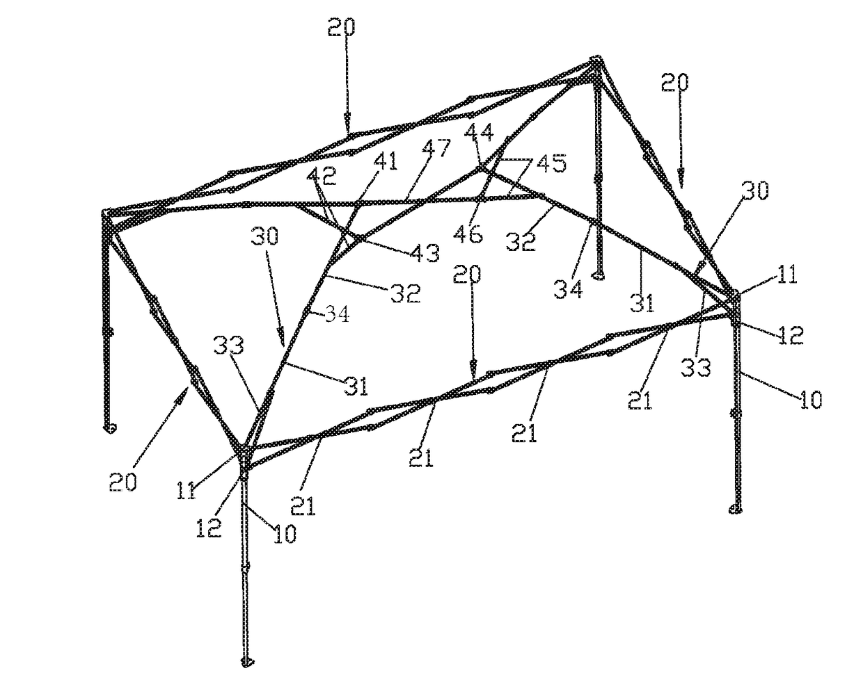
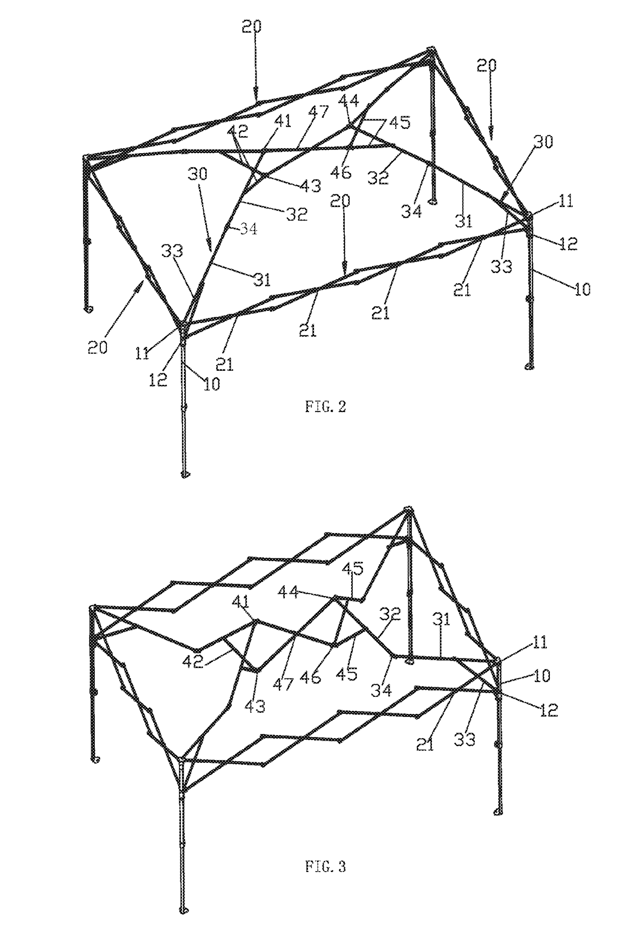
[0042]An awning mounting rack, referring to FIGS. 1-7, comprising four stand columns 10, the top end of each stand column 10 is disposed with a fixation set 11 fixedly, each stand column 10 is slidably disposed with a slide set 12; a lock device is disposed between the slide set 12 and the stand column 10 for locking and unlocking, when the lock device is released, the slide set 12 can be adjusted up and down with respect to the stand column 10, when the lock device is locked, the slide set is fixed with respect to the stand column 10. in this embodiment, the number of the stand columns 10 is preferred an even number, for example four, six, eight, etc, this embodiment takes four stand columns 10 for example.

[0043]These four stand columns 10 can be unfolded from the center to the outer side thus being far away respectively to each other, and they can be folded to the center thus being approach to each other, when in unfolding state, these stand columns are annular...

second embodiment

The Second Embodiment

[0049]The difference of the second embodiment from the first embodiment is that: referring to FIG. 8 and FIG. 9, the second folding bracket comprises two scissor type second linkworks 47 that are series connected. The series connecting means the same with above, in the second embodiment, there are two second linkworks 47.

third embodiment

The Third Embodiment

[0050]The difference of the third embodiment from the second embodiment is that: referring to FIGS. 10-14, the third embodiment further comprises a first reinforcing bracket 50, the first reinforcing bracket 50 comprises a first reinforcing pole 51, a second reinforcing pole 52 and a first driving pole 53.

[0051]Two first linkworks 21 of the first folding bracket 20 are series connected and pivoted, they have an upper pivot position and a second pivot position, the upper pivot position is a position that the upper ends of the link rods of two adjacent first linkworks are pivot joint together; the lower pivot position is a position that the lower ends of the link rods of two adjacent first linkworks are pivot joint together. One end of the first reinforcing pole 51 is rotatably connected to one end of the second reinforcing pole 52, the other end of the first reinforcing pole 51 is pivot joint to the first top set 41, the other end of the second reinforcing pole 52...


PUM


Abstract

An awning mounting rack includes four stand columns; a first folding bracket is disposed between two adjacent stand columns; each stand column has a top holder. The top holder includes a first pole, a second pole and a support pole. The four stand columns include two first stand columns and two second stand columns; the other ends of the second poles connected to the first stand columns are pivot joined to the first top set, the non-end portions of the second poles connected to the first stand columns are respectively pivot joined to a first support rod, the ends of the first support rods are pivot joined to a first bottom set; the other end of the second poles connected to the second stand column are pivot joined to a second top set, the non-end portions of the second poles are pivot joined to a second support rod.

Description

FIELD OF THE INVENTION[0001]The present invention relates an awning mounting rack, the awning and an awning top of the awning mounting rack.BACKGROUND OF THE INVENTION[0002]Existing known awning mounting rack, referring to FIG. 1, comprises four stand columns 10′, the top end of each stand column 10′ is disposed with a fixation set 11′ fixedly, each stand column 10′ is slidably disposed with a slide set 12′; a first folding bracket 20′ is pivoted and disposed between the fixation sets 11′ and the slide sets 12′ of two adjacent stand columns 10′; each stand column 10′ is connected to a top holder 30′, the top holder 30′ comprises a first pole 31′, a second pole 32′ and a support pole 33′, one end of the first pole 31′ is rotatably connected to one end of the second pole 32′, the other end of the first pole 31′ is pivot joint to the fixation set 11′, both ends of the support pole 33′ are respectively pivot joint to the slide set 12′ and a non-end portion of the first pole 31′; the oth...

Claims


Application Information

Patent Timeline
Patent Type & Authority Patents(United States)
IPC IPC(8): E04H15/50E04H15/46E04H15/52E04H15/18
CPCE04H15/50E04H15/52E04H15/46E04H15/18
Inventor HUANG, CHANGJIU
Owner XIAMEN ROADZUP OUTDOOR PROD
Why Eureka
Try Eureka