Electromagnetic monitoring and control of a plurality of nanosatellites

a technology of nanosatellites and electromagnets, applied in the direction of instruments, mechanical measurement arrangements, cosmonautic vehicles, etc., can solve the problems of large satellites that are impractical for nanosatellite use, requiring significant electrical power, and not allowing relative orientation of the two satellites

Active Publication Date: 2017-12-19
NASA
View PDF4 Cites 6 Cited by
  • Summary
  • Abstract
  • Description
  • Claims
  • Application Information

AI Technical Summary

Benefits of technology

[0008]A reference nanosatellite establishes a Cartesian or other three dimensional coordinate system (x,y,z) for an array of two or more nanosatellites, including the reference. One, tw

Problems solved by technology

At first impression, the number of independent equations appears to be less than the number of independent variables, such as location coordinates, which presents a problem for a complete specification.
The operating distances for previous applications requires significant electrical power.
A typical nanosatellite operates on 2.5-10 Watts of power, which makes a large satellite impractical for nanosatellite use.
When two satellites in such a system are pushing or pulling in unison, the dipoles are aligned, which doe

Method used


Image

  • Electromagnetic monitoring and control of a plurality of nanosatellites
  • Electromagnetic monitoring and control of a plurality of nanosatellites
  • Electromagnetic monitoring and control of a plurality of nanosatellites

Examples


Embodiment Construction

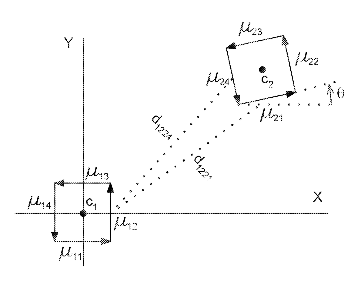
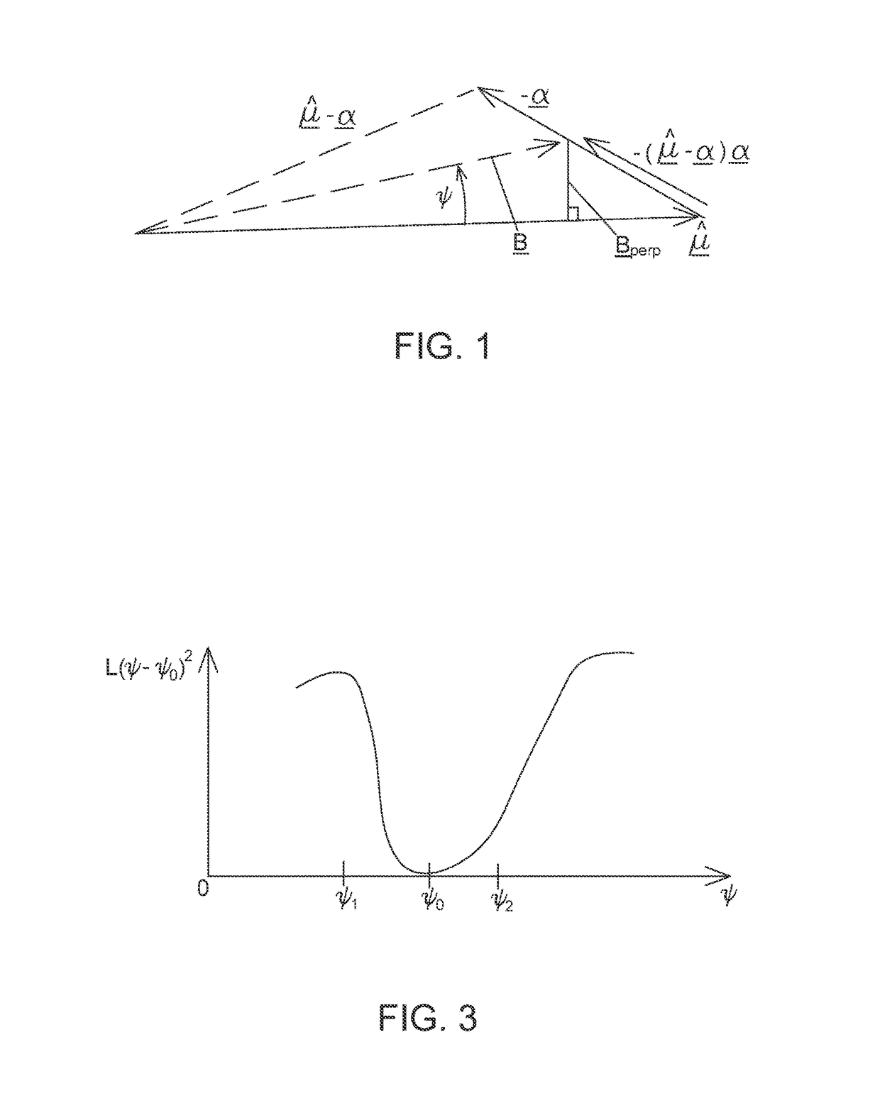
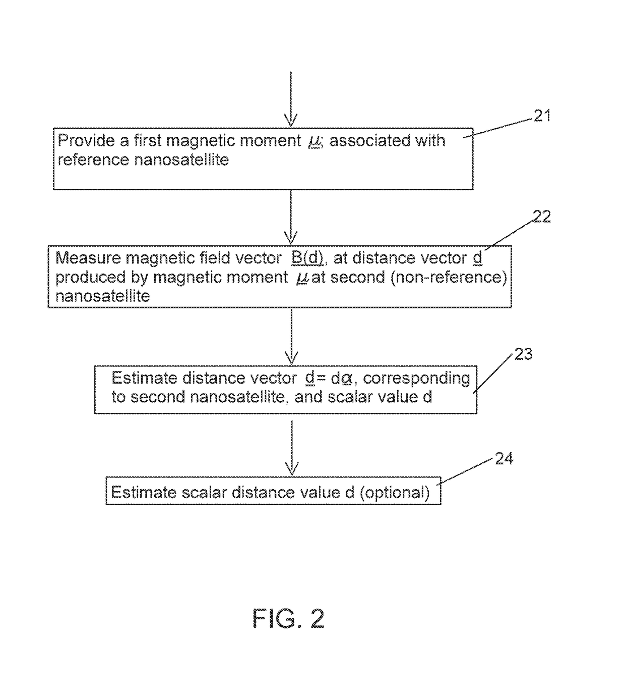
[0020]One challenge in monitoring and controlling one or more nanosatellites, using electromagnetic forces and torques, is determination of all relevant components of the three dimensional distance vectors that naturally arise in description of the physical parameters and resulting forces in such an environment. Beginning with the expression in Eq. (2) for a magnetic field flux that is generated by presence of a known magnetic moment μ, one is first confronted with estimation of the distance vector d (with source at a center of the magnetic moment source or associated solenoid(s)) at the point of measurement of the magnetic field B(d). Equation (2) is analyzed to estimate the vector components of d, using the known magnetic moment vector μ and the measurable field vector B(d). Equation (2) is rewritten as

B′(d)=(4π / μ0)B(d)={μ−(μ·d)d / d2} / d3={μ−(μ·α)α} / d3.  (3)

d=dα,  (4)

where α is a normalized vector (|α|=1) whose direction is parallel to the (unknown) direction of d. The normalized di...


PUM


Abstract

A method for monitoring position of and controlling a second nanosatellite (NS) relative to a position of a first NS. Each of the first and second NSs has a rectangular or cubical configuration of independently activatable, current-carrying solenoids, each solenoid having an independent magnetic dipole moment vector, μ1 and μ2. A vector force F and a vector torque are expressed as linear or bilinear combinations of the first set and second set of magnetic moments, and a distance vector extending between the first and second NSs is estimated. Control equations are applied to estimate vectors, μ1 and μ2, required to move the NSs toward a desired NS configuration. This extends to control of N nanosatellites.

Description

SOURCE OF THE INVENTION[0001]The invention described herein was made by an employee of the United States Government and may be manufactured and used by or for the Government of the United States of America for governmental purposes without the payment of any royalties thereon or therefore.FIELD OF THE INVENTION[0002]This invention relates to characterization and control of one or more nanosatellites by a designated control nanosatellite, using magnetic field measurements.BACKGROUND OF THE INVENTION[0003]Ideally, monitoring and controlling one or more of a plurality of nanosatellites relative to a reference body or reference position would allow (i) control of relative motion of each of the nanosatellites, (ii) power or energy transfer between two or more of the nanosatellites, and (iii) data communication between two or more of the nanosatellites. However, this monitoring of position requires reasonably accurate specification of vector coordinates of the nanosatellites that interact...

Claims


Application Information

Patent Timeline
IPC IPC(8): G01B7/00G01B7/30B64G1/24B64G1/10G01B5/02B64G1/36G01S5/02
CPCG01B7/003G01B7/30B64G1/1085G01S5/0284B64G1/366G01S5/0247B64G1/24B64G1/32G01B7/14
Inventor SOLOWAY, DONALD I.
Owner NASA
Why Eureka
Try Eureka