System for centralized monitoring and control of electric powered hydraulic fracturing fleet

a technology of electric powered hydraulic fracturing and fleet monitoring, applied in the field of hydraulic fracturing, can solve the problems of high cost of diesel fuel transportation between oilfield sites

Active Publication Date: 2016-02-04
US WELL SERVICS LLC
View PDF17 Cites 223 Cited by
  • Summary
  • Abstract
  • Description
  • Claims
  • Application Information

AI Technical Summary

Benefits of technology

[0006]Disclosed herein is a system for hydraulically fracturing an underground formation in an oil or gas well to extract oil or gas from the formation, the oil or gas well having a wellbore that permits passage of fluid from the wellbore into the formation. The system includes a plurality of electric pumps fluidly connected to the well, and configured to pump fluid into the wellbore at high pressure so that the fluid passes from the wellbore into the formation, and fractures the formation. The system also includes a plurality of generators electrically connected to the plurality of electric pumps to provide electrical power to the pumps. At least some of the plurality of generators can be powered by natural gas. In addition, at least some of the plurality of generators can be turbine generators. The system can also include a centralized control unit coupled to the plurality of electric pumps and the plurality of generators. The centralized control unit monitors at least one of pressure, temperature, fluid rate, fluid density, concentration, volts, amps, etc. of the plurality of electric pumps and the plurality of generators.
[0007]Also disclosed herein is a process for stimulating an oil or gas well by hydraulically fracturing a formation in the well. The process includes the steps of pumping fracturing fluid into the well with an electrically powered pump or fleet of pumps at a high pressure so that the fracturing fluid enters and cracks the formation, the fracturing fluid having a

Problems solved by technology

Such pumps are able to pump fracturing fluid into a wellbore at a high enough pressure to crack the formation, but they also have drawbacks.
For example, the diesel pumps are very heavy, and thus must be moved on heavy duty trailers, making transport of the pumps between oilfiel

Method used


Image

  • System for centralized monitoring and control of electric powered hydraulic fracturing fleet
  • System for centralized monitoring and control of electric powered hydraulic fracturing fleet
  • System for centralized monitoring and control of electric powered hydraulic fracturing fleet

Examples


Embodiment Construction

[0013]The foregoing aspects, features, and advantages of the present technology will be further appreciated when considered with reference to the following description of preferred embodiments and accompanying drawing, wherein like reference numerals represent like elements. In describing the preferred embodiments of the technology illustrated in the appended drawing, specific terminology will be used for the sake of clarity. However, the technology is not intended to be limited to the specific terms used, and it is to be understood that each specific term includes equivalents that operate in a similar manner to accomplish a similar purpose.

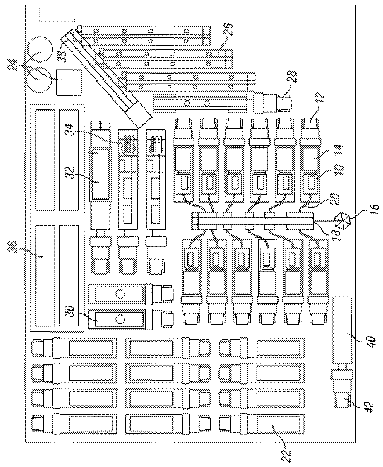
[0014]FIG. 1 shows a plan view of equipment used in a hydraulic fracturing operation. Specifically, there is shown a plurality of pumps 10 mounted to pump trailers 12. The pump trailers 12 can be trucks having at least two-three axles. In the embodiment shown, the pumps 10 are powered by electric motors 14, which can also be mounted to the pump t...


PUM


Abstract

A system and method are disclosed for centralized monitoring and control of a hydraulic fracturing operation. The system includes an electric powered fracturing fleet and a centralized control unit coupled to the electric powered fracturing fleet. The electric powered fracturing fleet can include a combination of one or more of: electric powered pumps, turbine generators, blenders, sand silos, chemical storage units, conveyor belts, manifold trailers, hydration units, variable frequency drives, switchgear, transformers, and compressors. The centralized control unit can be configured to monitor and/or control one or more operating characteristics of the electric powered fracturing fleet.

Description

CROSS-REFERENCE TO RELATED APPLICATION[0001]This application claims priority to and is a continuation-in-part of U.S. patent application Ser. No. 13 / 679,689, filed on Nov. 16, 2012 and titled “System for Pumping Hydraulic Fracturing Fluid Using Electric Pumps,” the content of which is incorporated herein by reference.BACKGROUND OF THE INVENTION[0002]This technology relates to hydraulic fracturing in oil and gas wells. In particular, this technology relates to pumping fracturing fluid into an oil or gas well using equipment powered by electric motors, as well as centralized monitoring and control for various controls relating to the wellsite operations.[0003]Hydraulic fracturing has been used for decades to stimulate production from oil and gas wells. The practice consists of pumping fluid into a wellbore at high pressure. Inside the wellbore, the fluid is forced into the formation being produced. When the fluid enters the formation, it fractures, or creates fissures, in the formatio...

Claims


Application Information

Patent Timeline
IPC IPC(8): E21B43/26E21B43/267
CPCE21B43/267E21B43/26E21B43/2607
Inventor BROUSSARD, JOEL N.MCPHERSON, JEFFKURTZ, ROBERTOEHRING, JAREDHINDERLITER, BRANDON
Owner US WELL SERVICS LLC
Why Eureka
Try Eureka