Automatic chemical feeding device and method in foam-drainage gas recovery well

A technology of foam drainage and automatic chemical dosing, which is applied in the direction of mining fluid, earthwork drilling, wellbore/well components, etc. It can solve the problems of insufficient drainage, increased drainage burden, rapid water flooding of gas wells, etc., and achieve improved automation Management level, avoiding water flooding of gas wells, and reducing work intensity

Inactive Publication Date: 2013-09-11
SOUTHWEST PETROLEUM UNIV
View PDF3 Cites 16 Cited by
  • Summary
  • Abstract
  • Description
  • Claims
  • Application Information

AI Technical Summary

Problems solved by technology

[0003] However, the current foaming agent filling process faces two common problems. One is that the downhole fluid information cannot be obtained in real time before dosing, and it is difficult to determine the best timing for dosing; the other is that the medicine is added from the wellhead, making the medicine float on the liquid surface Or it is difficult to reach the intended position and cannot mix well with the bottom fluid
This will bring about the following consequences: 1) If the fluid at the bottom of the well increases rapidly and the dosing is not timely, the gas well may be flooded rapidly; The medicine will also become a part of the effusion, increasing the burden of drainage; 3) The concentration of the medicine at the bottom of the effusion is too low, and the amount of foam produced is insufficient to fully drain the fluid

Method used


Image

  • Automatic chemical feeding device and method in foam-drainage gas recovery well
  • Automatic chemical feeding device and method in foam-drainage gas recovery well

Examples


Embodiment Construction

[0013] The present invention will be further described below in conjunction with accompanying drawing:

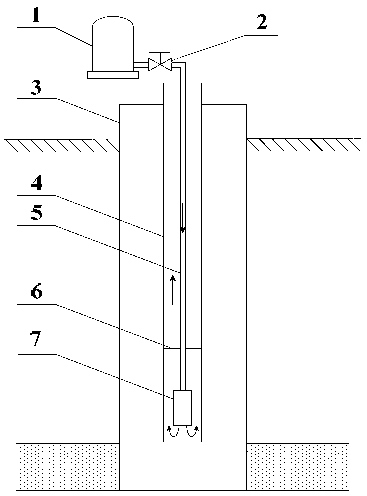
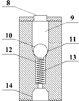
[0014] Such as figure 1 , figure 2 As shown, an automatic dosing device for foam drainage and gas recovery in the present invention is mainly composed of a medicine storage tank 1, a thin tube 5, a differential pressure control valve 7, an oil pipe 4, and a casing 3. The medicine storage tank 1, thin tube valve 2, thin tube 5, and differential pressure control valve 7 are sequentially connected in series from top to bottom to form a medicine adding channel. An annular drainage channel is formed between the thin tube 5 and the oil tube 4 . The differential pressure control valve 7 is mainly composed of a drug inlet 8, an upper chamber 9, a valve core ball 10, a conical valve seat 11, a lower chamber 12, a spring 13, and a drug outlet 14. The medicine inlet 8 is connected with the thin tube 5, and the medicine outlet 14 is communicated with the oil pipe 4; the spring 13 i...


PUM


Abstract

The invention relates to an automatic chemical feeding device and method in a foam-drainage gas recovery well. The automatic chemical feeding device mainly comprises a ground chemical storage tank, a thin pipe valve, a thin pipe, a pressure difference control valve, an oil pipe and a casing. The ground chemical storage tank, the thin pipe valve, the thin pipe and the pressure difference control valve form a chemical feeding channel, the thin pipe and the oil pipe form an annular liquid discharge channel, and the pressure difference control valve mainly comprises a chemical inlet, an upper cavity, a valve spool ball, a conical valve seat, a lower cavity, a spring and a chemical outlet. The upper end of the pressure difference control valve is stressed by chemical gravity (constant in pressure), and the lower end thereof is stressed by return pressure at bottom of the well. The more the accumulated liquid is, the higher the return pressure at the bottom of the well is and the lower the downward pressure difference stressed on the valve spool ball is, so that the spring can overcome the pressure difference to support the valve spool ball upwards and chemicals are begun to be added. After the accumulated liquid is discharged, the pressure difference is larger than elastic force of the spring and presses the valve spool ball to stop chemical feeding. The automatic chemical feeding device can automatically feed and stop feeding chemicals according to level of the accumulated liquid, and the chemicals and the accumulated liquid at the bottom can be guaranteed to be sufficiently mixed.

Description

technical field [0001] The invention relates to a dosing device and method for foam drainage and gas recovery used in gas wells, and belongs to the field of oil and gas exploitation. Background technique [0002] Natural gas wells in my country generally produce water. When a gas well enters the middle and late stages of production, the gas production decreases, gas-liquid slippage is serious, and water flows back to the bottom of the well to form fluid accumulation, which may easily cause the gas well to "flood" and stop production. Foam drainage gas recovery is one of the most economical and effective ways to prevent gas wells from accumulating liquid and maintain stable production of gas wells, and it is also the main means of fluid drainage and gas recovery in most of the gas fields in the middle and late stages in my country. It injects an appropriate amount of foaming agent into the wellbore, so that the bottom fluid can generate stable foam under the action of air flo...

Claims


Application Information

Patent Timeline
Patent Type & Authority Applications(China)
IPC IPC(8): E21B43/22
Inventor 钟海全刘通朱沫李颖川王志彬杨美华周永志
Owner SOUTHWEST PETROLEUM UNIV
Why Eureka
Try Eureka