Electrolyte chemistry control in electrodialysis processing

a technology of electrodialysis and electrolysis, applied in the field of electrodialysis, can solve the problems of high concentration of soluble calcium, scale formation, and high difficulty in applying electrodialysis processing to the treatment or processing of highly concentrated brines, and achieve the effect of improving electrodialysis and minimizing cation fouling

Active Publication Date: 2017-12-26
GAS TECH INST
View PDF2 Cites 1 Cited by
  • Summary
  • Abstract
  • Description
  • Claims
  • Application Information

AI Technical Summary

Benefits of technology

[0019]A general object of the invention is to provide improved electrodialysis and, more particularly, to minimization of cation fouling in electrodialysis processing.
[0023]Another aspect of the invention relates to specific improvements in electrodialysis units that include an anode and a cathode each in an electrolyte of a selected concentration and a membrane stack disposed therebetween, the membrane stack comprising pairs of cationic selective and anionic membranes to segregate increasingly dilute salts streams from concentrated salts stream. As detailed below, in one embodiment such improvement involves placement of a single calcium exclusionary cationic selective membrane at a cathode cell boundary to minimize transport of multivalent cations into the cathode cell.

Problems solved by technology

The application of electrodialysis processing to the treatment or processing of highly concentrated brines, especially those that contain a high concentration of soluble calcium, or other multivalent cations, can be particularly challenging.
For example, a practical problem in applying electrodialysis to the treatment of waters with calcium levels in the range of up to or about 100 mg / l is that a significant flux of calcium can occur through the cationic membrane from the stack cell adjacent to the cathode electrolyte cell to cause scale to form on the cathode and cause precipitates of calcium sulfate and other divalent sulfates to form in the electrolyte solution.
This greatly reduces the effective amperage and the rate of ion flux in the electrodialysis stack.
This would be deleterious to the overall performance of the process.

Method used


Image

  • Electrolyte chemistry control in electrodialysis processing
  • Electrolyte chemistry control in electrodialysis processing
  • Electrolyte chemistry control in electrodialysis processing

Examples


Embodiment Construction

[0030]The present invention provides improved electrodialysis and, more particularly, to improved electrolyte chemistry control in electrodialysis processing

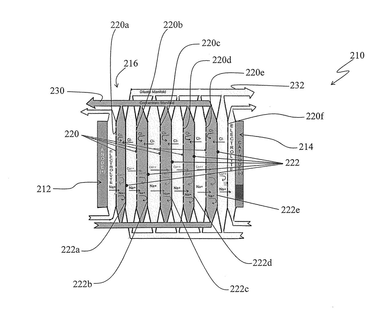
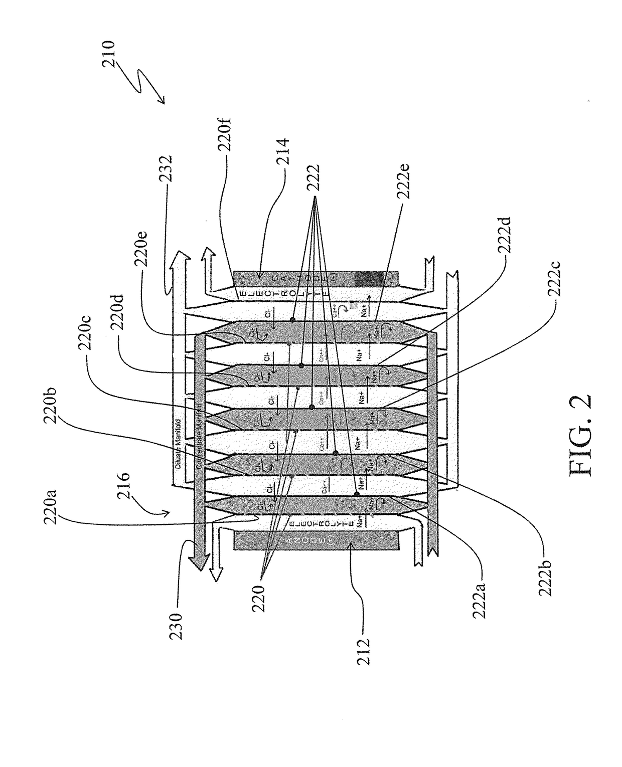
[0031]Turning to FIG. 2, there is shown a simplified schematic of an electrodialysis membrane stack arrangement, generally by the reference 210, in accordance with one aspect of the invention.

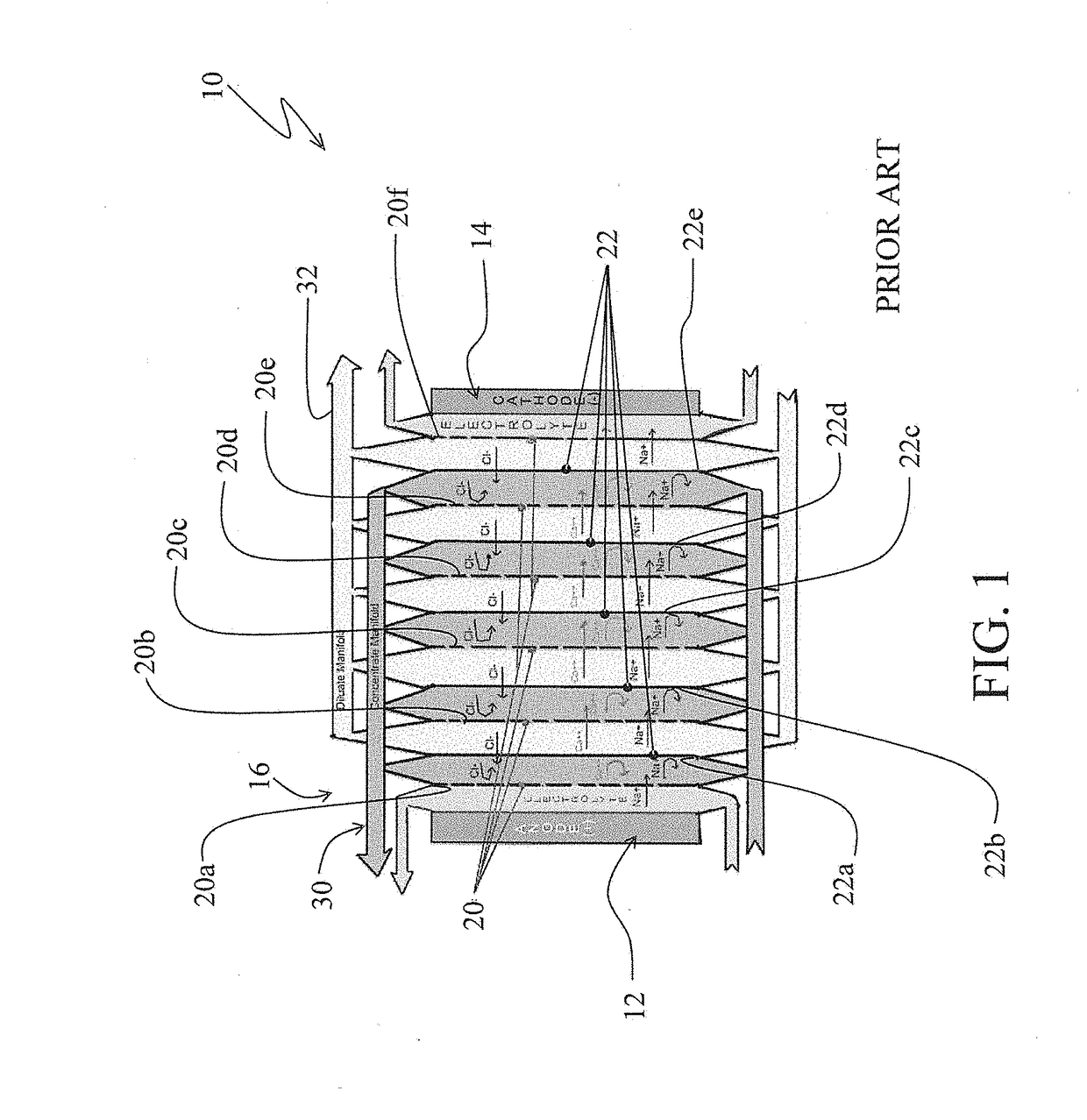
[0032]The electrodialysis membrane stack arrangement 210 is somewhat similar to the electrodialysis membrane stack arrangement 10 shown in FIG. 1 and discussed above. For example, the electrodialysis membrane stack arrangement 210 similar to the electrodialysis membrane stack arrangement 10 includes an anode electrode cell 212, a cathode electrode cell 214 and a membrane stack 216 appropriately disposed between the anode and the cathode cells. Also, the membrane stack 216 includes alternating cationic selective membranes 220 (and specifically identified by the references 220a, 220b, 220c . . . ) and anionic selective membranes 222 (and spec...


PUM


Abstract

Methods for controlling electrolyte chemistry in electrodialysis units having an anode and a cathode each in an electrolyte of a selected concentration and a membrane stack disposed therebetween. The membrane stack includes pairs of cationic selective and anionic membranes to segregate increasingly dilute salts streams from concentrated salts stream. Electrolyte chemistry control is via use of at least one of following techniques: a single calcium exclusionary cationic selective membrane at a cathode cell boundary, an exclusionary membrane configured as a hydraulically isolated scavenger cell, a multivalent scavenger co-electrolyte and combinations thereof.

Description

STATEMENT REGARDING FEDERALLY SPONSORED RESEARCH OR DEVELOPMENT[0001]This invention was made with government support under grant DE-AC26-07NT42677 awarded by the Department of Energy (DOE). The government has certain rights in the invention.BACKGROUND OF THE INVENTION[0002]This invention relates generally to electrodialysis and, more particularly to electrolyte chemistry control in electrodialysis processing[0003]Electrodialysis is a membrane separation technology in which stacked pairs of selective cationic and anion selective membranes are typically used to segregate increasingly dilute salt streams from concentrated salt streams. Stacks of membrane pairs can be very large and can include 10 to 100 or more pairs of alternating membranes. At one end of the stack, electrochemical reactions are produced by a cathode in electrolyte solution. At the other end of the stack, another reaction is created by an anode in electrolyte solution. In the usual process, the electrolyte stream is s...

Claims


Application Information

Patent Timeline
Patent Type & Authority Patents(United States)
IPC IPC(8): B01D61/44B01D61/46B01D61/54B01D65/08
CPCB01D61/46B01D61/44B01D65/08B01D61/54B01D2313/32B01D61/463
Inventor HAYES, THOMAS D.SEVERIN, BLAINE F.
Owner GAS TECH INST
Why Eureka
Try Eureka