
Electrolyte chemistry and improved stack performance in high brine concentration electrodialysis

a high brine concentration, electrolyte technology, applied in the field of electrolysis, can solve the problems of preventing efficient ion transfer, unable to proceed with electrolyte, affecting the efficiency of ion transfer, etc., and achieve the effects of improving stack performance and electrolyte chemistry, improving electrodialysis, and improving electrolyte chemistry

Active Publication Date: 2019-08-27
GAS TECH INST
View PDF12 Cites 0 Cited by
  • Summary
  • Abstract
  • Description
  • Claims
  • Application Information

AI Technical Summary

Benefits of technology

[0023]A general object of the invention is to provide improved electrodialysis and, more particularly, improved stack performance and electrolyte chemistry and in high brine concentration electrodialysis.
[0025]In accordance with one aspect of the invention there is provided, a method for improving ion flux and energy efficiency in an electrodialysis unit membrane stack. In accordance with one embodiment, a suitable electrodialysis unit includes an anode and a cathode each in an electrolyte of a selected concentration with the membrane stack disposed therebetween. The membrane stack includes pairs of cationic selective and anionic membranes to segregate increasingly dilute salts streams from concentrated salts stream. As detailed further below, ion flux and energy efficiency in the stack can be improved through or by using at least one selected from the group consisting of increasing the concentration of the electrolyte, adding a strong base to the electrolyte and adding buffering anions to the electrolyte.
[0027]In accordance with another aspect of the invention, there is provided a method for improving operation in an electrodialysis unit. The electrodialysis unit includes an anode and a cathode electrode each in an electrolyte of a selected concentration and a membrane stack disposed therebetween. The membrane stack includes pairs of cationic selective and anionic membranes to segregate increasingly diluted salt treated water stream from concentrated salts stream. In one embodiment such a method for improving operation involves suitably applying heat to increase the operating temperature of at least one of the electrolyte and the treated water stream.

Problems solved by technology

Without initiation of the electrolysis reaction, electrodialysis cannot proceed.
In practice, there are several junctions within conventional electrodialysis processing that will or can impede efficient ion transfer.
This can cause transfer of hydrogen ions and hydroxide ions across the respective membrane instead of the beneficial transfer of salt ions.
Thus, amperage is generated by transfer of non-beneficial ions caused by the water splitting.
This condition can be destructive to the membranes for a variety of reasons.
However, when electrodialysis is used or applied at conditions to treat heavy brine or high salt concentrations (e.g., brine containing 1-8% salt down to 0.5% salt; i.e., low voltage and high amperage) such operation is very far from the “limiting current” conditions that pertain to conventional operation.
Thus, such operation presents challenges and issues not addressed by conventional practice or operation.
Under such conditions, ion flux is usually limited by the “limiting current” at the membrane interfaces within the membrane stack.
Thus, at this limiting current condition, power is wasted by transferring hydrogen ion instead of the target cation (example: sodium ion) and / or hydroxide ion instead of the target anion (example: chloride).
The polarized water also can cause rapid degradation of the membrane materials.
The loss of H+ in the catholyte causes an ion imbalance that requires the transport of a cation (e.g., sodium ion) from the membrane stack into the cathode cell.
The result is that the catholyte becomes basic and sodium rich while the anolyte becomes acidic and sodium poor.
However, the application of electrodialysis to high brine conditions, i.e., 0.5% to 8% TDS, presents many and various challenges.
For example, with the application of electrodialysis to high brine conditions the opportunities to create a “limiting current” condition at the membrane surfaces are typically severely limited as the ionic strength of the solution is so high.
Precipitation of calcium and barium as hydroxides or sulfates, or the precipitation of iron as a hydroxide at the electrodes is problematic and can result in a rapid increase in resistance to ion flux at the surface of the electrode.
Conventional washing typically requires significant down time.
An additional disadvantage of conventional cleaning is the need for handling and storage of strong chemical cleaning agents.
Further, while pole reversal has previously been applied during conventional electrodialysis, such conventional practice has typically involved switching the polarity of the electrode for extended periods of time, up to several hours per switch.

Method used


Image

  • Electrolyte chemistry and improved stack performance in high brine concentration electrodialysis
  • Electrolyte chemistry and improved stack performance in high brine concentration electrodialysis
  • Electrolyte chemistry and improved stack performance in high brine concentration electrodialysis

Examples


Embodiment Construction

[0040]The present invention provides improved electrodialysis and, more particularly, improved stack performance and electrolyte chemistry and in high brine concentration electrodialysis.

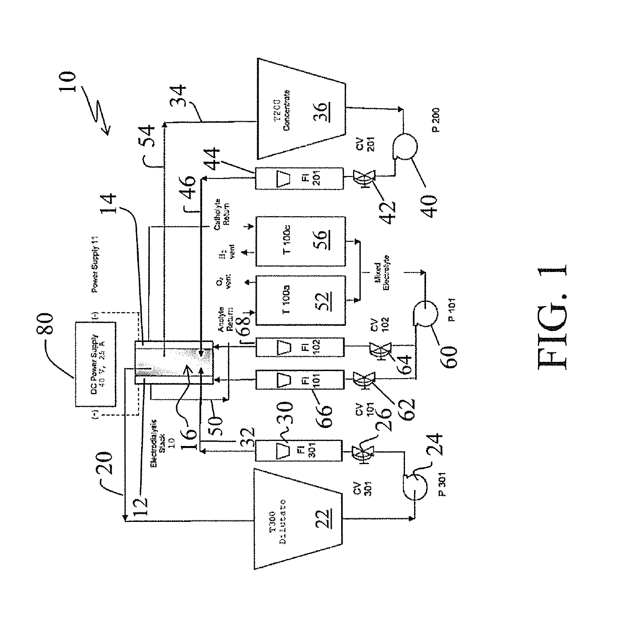
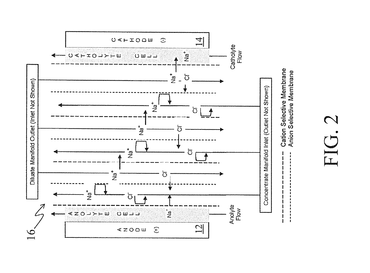
[0041]Turning to FIG. 1, there is shown a simplified flow diagram of an electrodialysis pilot plant, generally designated by the reference numeral 10, in accordance with one aspect of the invention. Main components of the electrodialysis plant 10 include an anode electrode cell 12, a cathode electrode cell 14 and a membrane stack (also sometimes simply referred to as a “stack”) 16 appropriately disposed between the anode and the cathode cells.

[0042]The membrane stack 16 is shown in greater detail in FIG. 2 and described further below.

[0043]As shown in FIG. 1, the diluate recovered from the membrane stack 16 is passed via a line 20 and is collected in a diluate tank 22. A pump 24, a control valve 26, and a rotometer 30 are used to appropriately deliver and control the flow of diluate via a line 32 to...


PUM


Abstract

Methods for improving ion flux and energy efficiency in a membrane stack of an electrodialysis unit wherein the membrane stack is disposed between an anode and a cathode each in an electrolyte of a selected concentration. Methods include increasing the concentration of the electrolyte, adding a strong base to the electrolyte and adding buffering anions to the electrolyte. Methods for cleaning the electrodes of such a unit involving involve applying a pulsed polarity reversal to the electrodes. Also provided are methods for improving unit operation by increasing the basicity of the electrolyte to the anode and increasing the acidity of the electrolyte to the cathode or alternatively or in addition, by applying heat to increase the operating temperature of at least one of the electrolyte and the treated water stream.

Description

STATEMENT REGARDING FEDERALLY SPONSORED RESEARCH OR DEVELOPMENT[0001]This invention was made with government support under grant DE-AC26-07NT42677 awarded by the Department of Energy (DOE). The government has certain rights in the invention.BACKGROUND OF THE INVENTION[0002]This invention relates generally to electrodialysis and, more particularly to electrodialysis employing high brine concentrations.[0003]Electrodialysis is a membrane separation technology in which stacked pairs of selective cationic and anion selective membranes are typically used to segregate increasingly dilute salt streams from concentrated salt streams. Stacks of membrane pairs can be very large and can include 10 to 100 or more pairs of alternating membranes. At one end of the stack, electrochemical reactions are produced by a cathode in electrolyte solution. At the other end of the stack, another reaction is created by an anode in electrolyte solution. In the usual process, the electrolyte stream is separate...

Claims


Application Information

Patent Timeline
Patent Type & Authority Patents(United States)
IPC IPC(8): B01D61/54B01D61/52B01D61/42B01D65/02
CPCB01D61/52B01D65/027B01D2311/12B01D2311/246B01D2313/345B01D2321/22B01D2321/223
Inventor HAYES, THOMAS D.SEVERIN, BLAINE F.
Owner GAS TECH INST
Learn More