
Sheet discharging apparatus, sheet processing apparatus, and image forming system

a technology of discharging apparatus and processing apparatus, which is applied in the direction of transportation and packaging, thin material processing, and article delivery, etc., can solve the problem that the sheet is easily changed disadvantageously, and achieves the effect of improving sheet stacking performance and keeping productivity

Pending Publication Date: 2022-05-26
CANON KK
View PDF0 Cites 0 Cited by
  • Summary
  • Abstract
  • Description
  • Claims
  • Application Information

AI Technical Summary

Benefits of technology

The patent invention offers a sheet discharging apparatus, sheet processing apparatus, and image forming system that can improve the way sheets of paper are stacked while keeping the productivity high.

Problems solved by technology

As a result, the stacking position of sheets discharged onto a destination, such as a discharging tray, to which the sheets are discharged tends to be easily changed disadvantageously.

Method used


Image

  • Sheet discharging apparatus, sheet processing apparatus, and image forming system
  • Sheet discharging apparatus, sheet processing apparatus, and image forming system
  • Sheet discharging apparatus, sheet processing apparatus, and image forming system

Examples


first embodiment

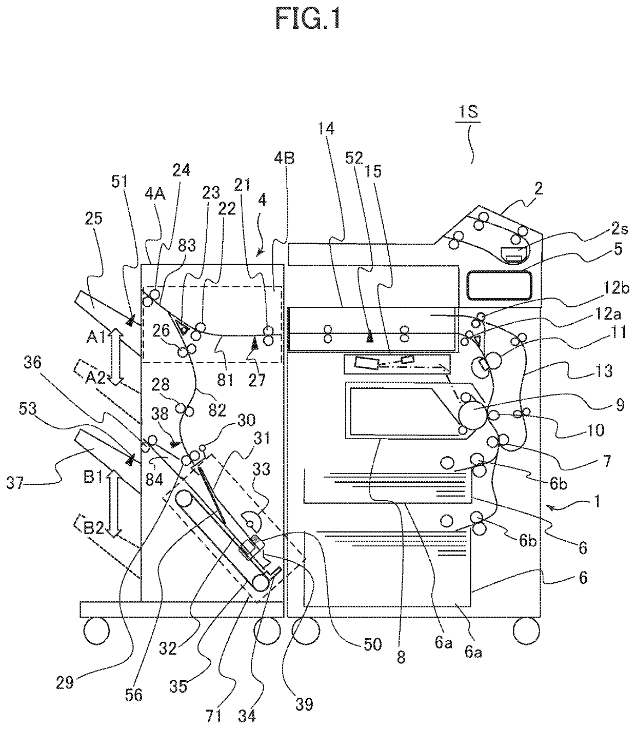
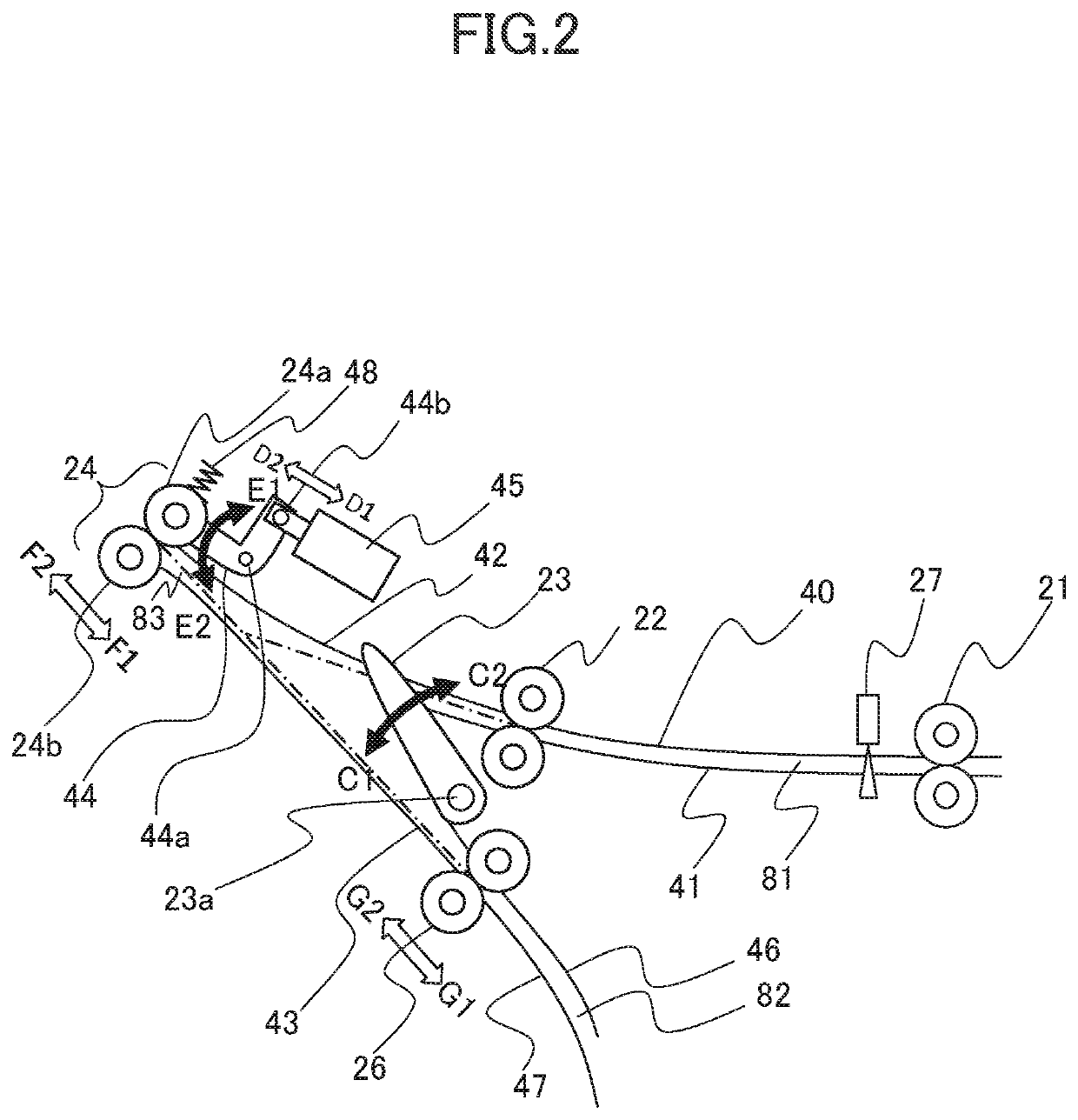
[0029]FIG. 1 is a schematic diagram of an image forming system 1S of a first embodiment, viewed from the front side of the image forming system 1S. The image forming system 1S includes an image forming apparatus 1 that forms an image on a sheet, a sheet processing apparatus 4 that performs processes on the sheet on which the image is formed by the image forming apparatus 1, a relay unit 14 that conveys the sheet from the image forming apparatus 1 to the sheet processing apparatus 4, and an image reading apparatus 2. The sheet, which is a recording material, may be a paper sheet, such as a plain paper sheet or a thick paper sheet, a plastic film, a cloth sheet, a sheet material, such as a coated paper sheet, on which certain surface treatment has been performed, a specially-shaped sheet material, such as an envelope or an index paper sheet, or any one of a variety of sheets having different sizes and materials. Hereinafter, the operation of each component of the image forming system ...

second embodiment

[0122]In the above-described first embodiment, the description has been made for the method of increasing the stacking performance by performing the superimposing-discharge operation that superimposes and discharges sheets. In a second embodiment, a wait position of one sheet on which another sheet to be superimposed is changed in accordance with the length of the one sheet in the conveyance direction, in the superimposing-discharge operation described in the first embodiment. Hereinafter, a component given a symbol identical to a symbol of the first embodiment is regarded as a component having the same structure and effect as those of the first embodiment, and the description thereof will be omitted.

[0123]In the bundle discharge operation described in the first embodiment, the conveyance direction of the preceding sheet S1 is reversed and the sheet S1 is stopped at a position (FIG. 5D), through the operations illustrated in FIGS. 5A to 5D. Hereinafter, the description will be made ...


PUM

PropertyMeasurementUnit
Lengthaaaaaaaaaa
Timeaaaaaaaaaa
Gravityaaaaaaaaaa

Abstract

A sheet discharging apparatus includes a stacking portion, a first conveyance portion, a detection portion, a second conveyance portion, a third conveyance portion, and a control portion. The control portion is configured to execute a discharge operation by causing the sheet discharging apparatus to reverse a conveyance direction of a first sheet conveyed from the first conveyance portion to the second conveyance portion and deliver the first sheet to the third conveyance portion by using the second conveyance portion, convey the first sheet toward the second conveyance portion by the third conveyance portion, and discharge the first sheet and the second sheet to the stacking portion by using the second conveyance portion in a state where the first sheet and the second sheet are superimposed on each other.

Description

BACKGROUND OF THE INVENTIONField of the Invention[0001]The present invention relates to a sheet discharging apparatus that discharges sheets, a sheet processing apparatus that performs processes on sheets, and an image forming system that forms images on sheets.Description of the Related Art[0002]A known image forming system includes a sheet processing apparatus (referred to also as a finisher) that performs processes, such as sort process, binding process, or alignment process, on sheets on which images have been formed. The sheet processing apparatus is available as an option of an image forming apparatus, such as an electrophotographic copying machine or a laser beam printer. In a case where the sheet processing apparatus performs a process on a plurality of sheet bundles successively, if the sheet processing apparatus temporarily stops receiving a sheet from the image forming apparatus until the sheet processing apparatus completes to perform the process on a preceding sheet bun...

Claims


Application Information

Patent Timeline
IPC IPC(8): B65H29/60B65H43/08B65H31/30
CPCB65H29/60B65H2801/06B65H31/3081B65H43/08B65H29/20B65H29/58B65H31/24B65H2801/39B65H2801/03B65H29/125B65H2301/4212B65H2301/42194B65H2801/27B65H2403/942B65H31/02B65H2405/11151B65H31/36B65H2404/1442B65H2404/1521B65H29/14
Inventor SUGAI, NOBUTOSHIMITA, TAKURO
Owner CANON KK
Learn More