Printing device

a printing device and printing technology, applied in the direction of electrographic process, instruments, transportation and packaging, etc., can solve the problems of decreasing productivity in the printing device, reducing the sound of a sheet against the registration roller, and reducing the transfer speed. , the effect of reducing the productivity of the printing devi

Active Publication Date: 2012-06-28
RISO KAGAKU CORP
View PDF2 Cites 6 Cited by
  • Summary
  • Abstract
  • Description
  • Claims
  • Application Information

AI Technical Summary

Benefits of technology

[0010]However, in the technique of this Patent Document, although the hitting sound of a sheet against the registration roller can be reduced, th

Problems solved by technology

However, in the technique of this Patent Document, although the hitting sound of a sheet against the registration roller can be reduced, the t

Method used


Image

  • Printing device
  • Printing device
  • Printing device

Examples


Embodiment Construction

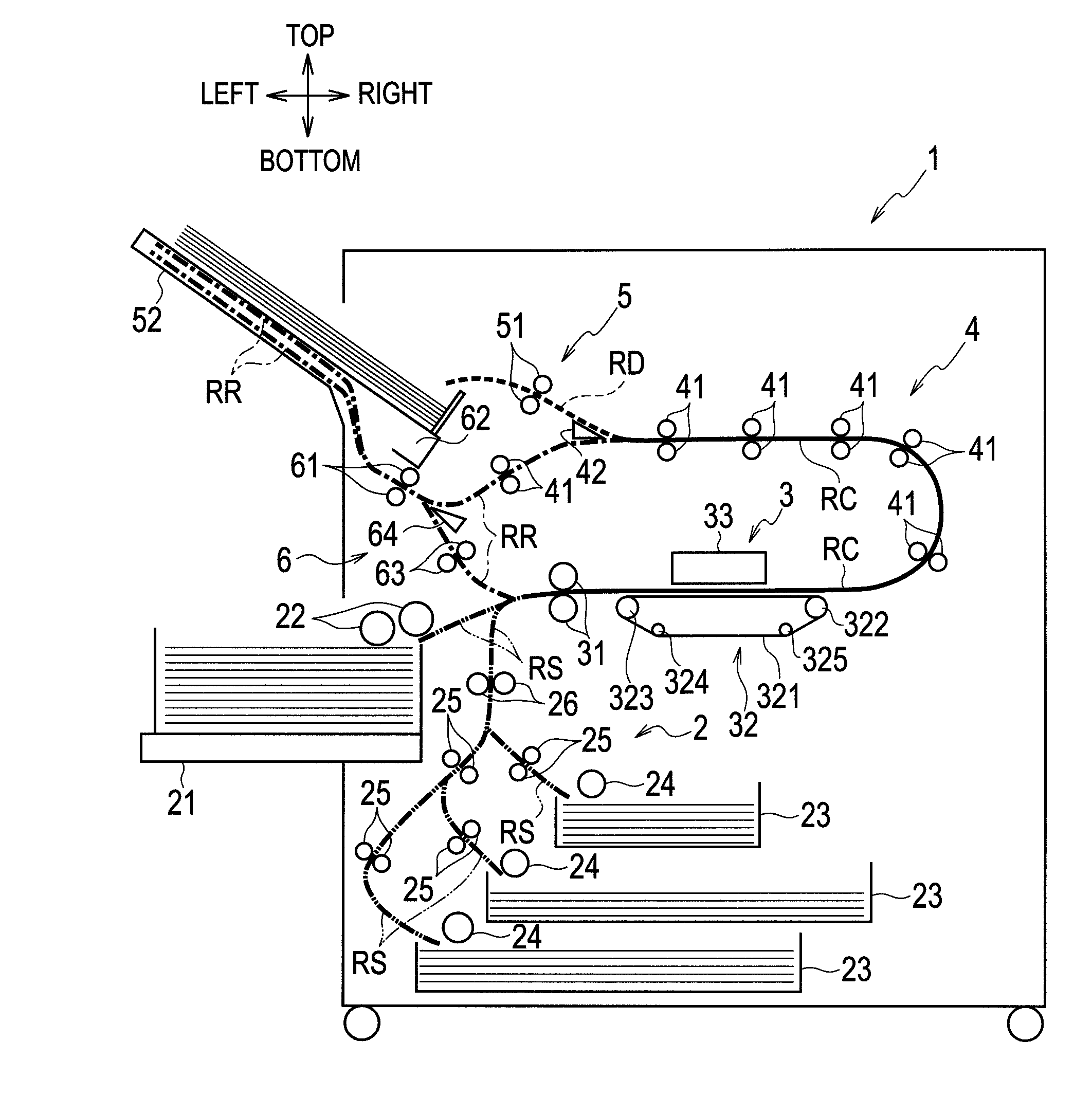
[0019]An embodiment of the present invention will be described below with reference to the accompanying drawings. Throughout the respective drawings, the same or equivalent reference numerals are assigned to the same or equivalent components. Note that the embodiment described in the drawings is schematic only and different from the real one.

[0020]Moreover, this embodiment exemplifies a device and the like for embodying the technical thought of the present invention. However, the technical thought of the present invention shall not be construed as limiting the arrangement and the like of the respective components to the following ones. The technical thought of the present invention may be modified within the original scope of the present application.

[0021]

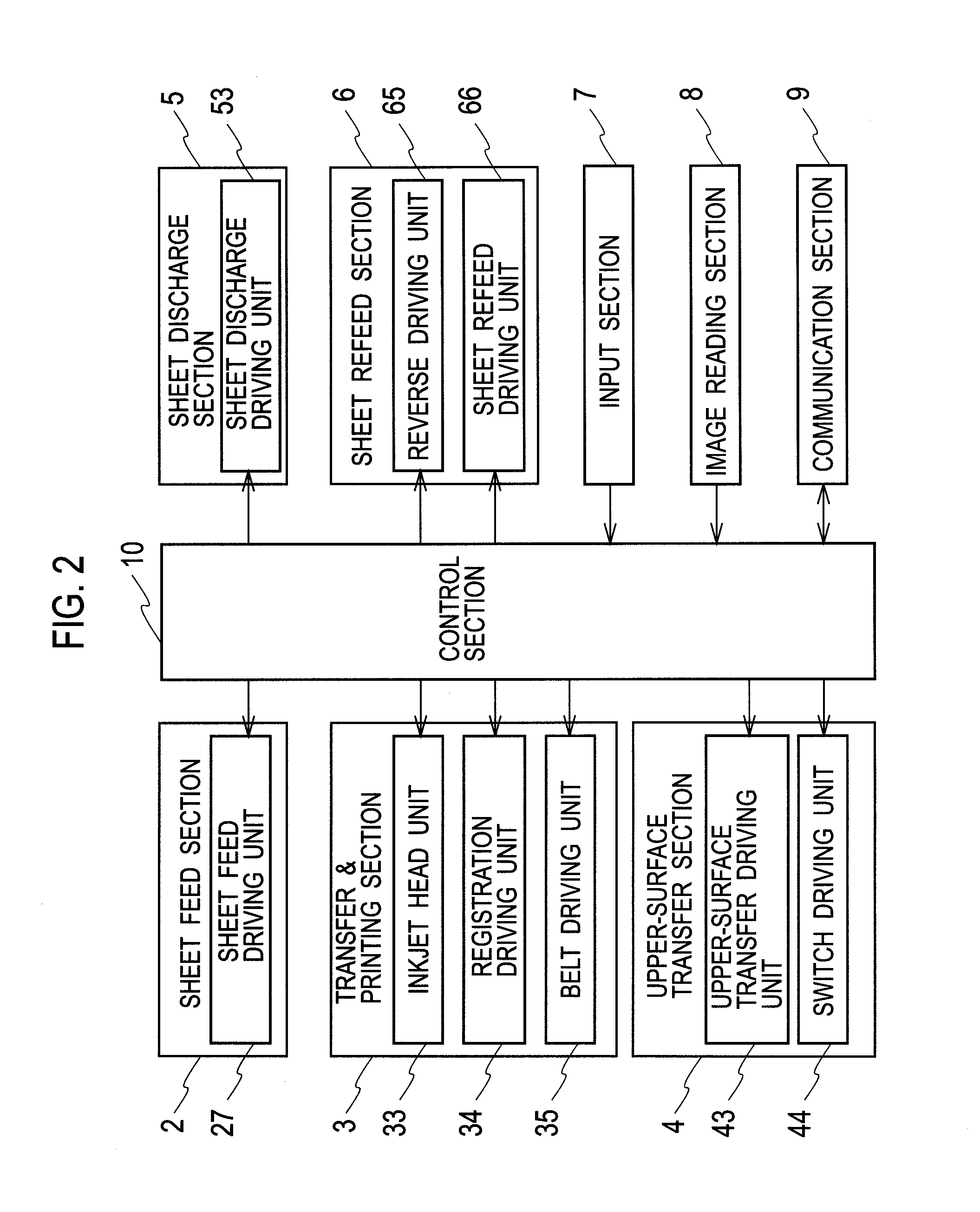
[0022]FIG. 1 is a schematic configuration diagram of a printing device according to an embodiment of the present invention. FIG. 2 is a block diagram showing the configuration of a control system of the printing device shown in FIG...


PUM


Abstract

A printing device includes: a registration roller that once stops a transferred sheet and then feeds the transferred sheet toward an inkjet head unit; a sheet feed system that transfers and feeds a sheet to the registration roller; a sheet refeed system that, during both-side printing, reverses a one-side printed sheet and transfers the one-side printed sheet to the registration roller; and a controller that, during both-side printing, controls the registration roller so as to feed a sheet, which is fed by the sheet feed system and the sheet refeed system, toward the inkjet head unit in accordance with a predetermined print schedule. The controller controls the sheet feed system in accordance with the print schedule so that a speed when a sheet fed from the sheet feed system is abutted against the inkjet head unit becomes lower during both-side printing than during one-side printing.

Description

BACKGROUND OF THE INVENTION[0001]1. Technical Field[0002]The present invention relates to printing devices that perform printing onto a sheet and the like, and in particular relates to a technique to reduce the noise generated by the printing devices.[0003]2. Background Arts[0004]There is conventionally known printing device having a feeding mechanism, in which a sheet extracted from a sheet feed stand is fed toward a printing section including an inkjet head and the like by a registration roller.[0005]In this printing device, a sheet is abutted against the registration roller and stopped once so as to form sag in the sheet, and then an oblique motion of the sheet is corrected. Then, the printing device drives the registration roller at a predetermined timing to feed the sheet to the printing section.[0006]When a sheet is abutted against the registration roller, a hitting sound is generated. In addition, when a sheet is fed by the registration roller and sag in the sheet is released...

Claims


Application Information

Patent Timeline
IPC IPC(8): B65H9/00
CPCB65H9/006B65H85/00B65H2511/414B65H2513/10B65H2801/06B65H2220/02B65H2220/01
Inventor YAMAGISHI, RYOTAKUSUHATA, MASAHIKOHARA, MASASHI
Owner RISO KAGAKU CORP
Why Eureka
Try Eureka