Split gusset connection

a gusset connection and split technology, applied in the direction of girders, joists, trusses, etc., can solve the problems of structural weight, material requirements, and significant cost increase, and achieve the effect of reducing the number of gussets

Active Publication Date: 2018-01-02
SHUHAIBAR CONSTANTINE
View PDF21 Cites 23 Cited by
  • Summary
  • Abstract
  • Description
  • Claims
  • Application Information

AI Technical Summary

Benefits of technology

[0041]One advantage of the invention is the ability to weld the gusset plates 202a / 202b to the beam Bm and column C in a shop (i.e., off the construction site) and simply assemble the components using the bolts 202 in the field (i.e., field bolting on the construction site). The prior art arrangement in FIG. 1 requires welding on the construction site, which is less reliable and accurate, less controlled, more costly, and more time-consuming than shop welding. In an ideal situation, structural members are prefabricated as much as possible and little to no structural connecting via welding is required at the construction site. For these reasons and more, shop welding and field bolting are strongly preferred in the construction industry.

Problems solved by technology

In extreme situations these large internal forces can fracture the beam, the beam to column bolted / welded assembly, the column, and / or the gusset welds, if the prior art connection parts are not designed accordingly.
However, if all the prior art connection parts are designed to accommodate the large internal forces, then structure weight, material requirements, and cost increase significantly.

Method used


Image

  • Split gusset connection
  • Split gusset connection
  • Split gusset connection

Examples


Embodiment Construction

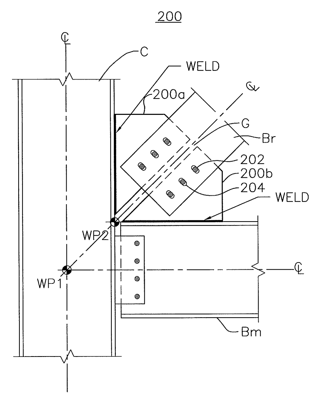
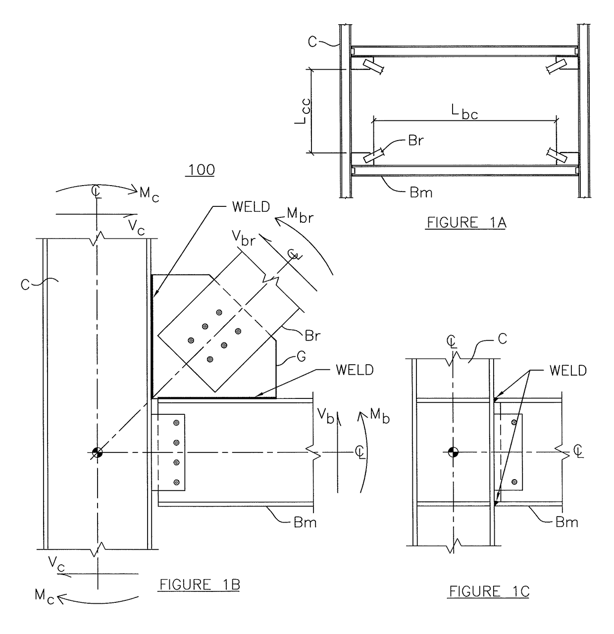
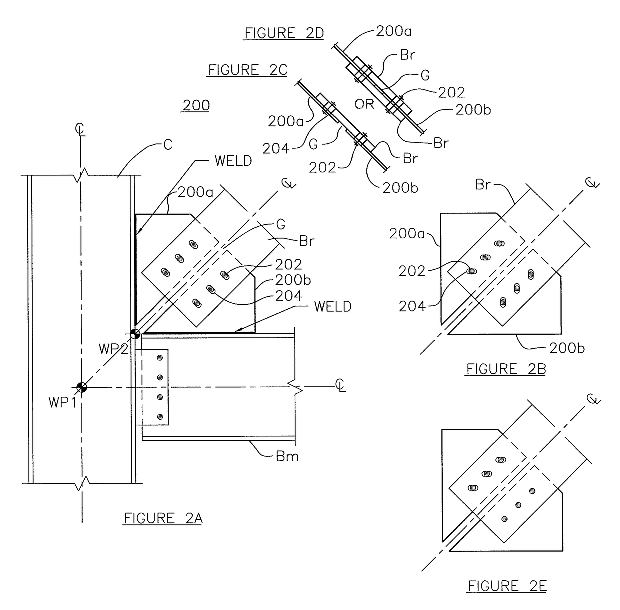
[0030]Embodiments of the invention include a gusset that adds minimal stress to all components it is connected to, such as a beam and column. In this case, the beam, column, and brace see minimal increases in their stresses by adding our gusset. Thus, the advantage of the prior art gusset (to enable brace beam coupling to a column and beam joint) is maintained, while the unwanted force transfer attributes of the prior art gusset (due to large earthquake-like forces) are in large part negated. Accordingly, for a structure having a beam / column / brace joint, when external forces (e.g., earthquake forces) are applied, the inventive gusset will not transfer movement of the beam to the column, movement of the column to the beam, and movement of the brace to the beam and / or column—as would a standard gusset connection. Thus, force transfer between the column, beam, and brace will occur as if the inventive gusset was not present, but instead will mimic true dynamic loads around an imaginary ...


PUM


Abstract

A gusset connection that allows greater relative movement between connected structural members and simplifies erection in the field. The gusset connection can be a first gusset portion moveably or fixedly connected to a vertical column and a second gusset connection moveably or fixedly connected to a horizontal beam. A diagonal brace is moveably or fixedly connected to the gusset connection. The first and second gusset portions are not directly connected to each other to allow relative movement between the column, beam, and diagonal brace.

Description

CROSS-REFERENCES TO RELATED APPLICATIONS[0001]This application is the National Stage of International Application No. PCT / US12 / 25122, filed on Feb. 14, 2012, which claims the benefit of U.S. Provisional Application No. 61 / 442,738, filed Feb. 14, 2011, which is incorporated by reference herein.BACKGROUND[0002]This invention generally concerns a structural joint, and more specifically concerns a gusset connection that allows greater relative movement between connected structural members and simplifies erection in the field.[0003]FIG. 1A shows a typical prior art gusset connection in a braced frame structure. A horizontal structural member Bm (beam) is connected to a vertical structural member C (column). To connect the diagonal structural member Br (i.e., brace) to the beam-column assembly, a gusset plate G is used. The brace is connected (e.g., pinned, bolted) to the gusset and the gusset is connected to both the beam and the column, typically by welding. Length Lcc is the clear leng...

Claims


Application Information

Patent Timeline
Patent Type & Authority Patents(United States)
IPC IPC(8): E04B1/24E04H9/02E04C3/04
CPCE04B1/2403E04B1/24E04B2001/2415E04B2001/2439E04H9/028E04B2001/2463E04B2001/2496E04C2003/0491E04B2001/2448E04H9/0237E04B1/38E04B1/58
Inventor SHUHAIBAR, CONSTANTINE
Owner SHUHAIBAR CONSTANTINE
Why Eureka
Try Eureka