

Apparatus and method for generating and moving a magnetic field having a field free line
a magnetic field and apparatus technology, applied in the field of apparatus and method for generating and changing a magnetic field, can solve the problems of not being able to achieve, significant power loss, etc., and achieve the effect of less power loss
- Summary
- Abstract
- Description
- Claims
- Application Information
AI Technical Summary
Benefits of technology
Problems solved by technology
Method used
Image

Examples
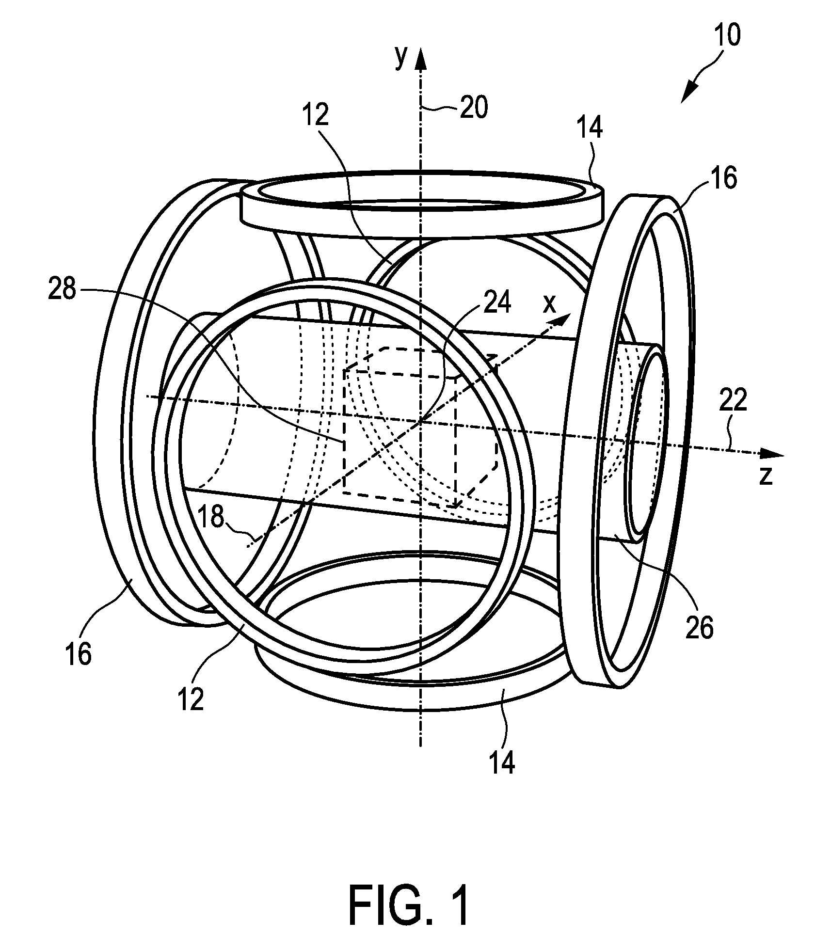
embodiment 10
[0060]The embodiment 10 of the MPI scanner has at least one further pair, preferably three further pairs, of parallel circular coils, again oriented along the x-, y-, and z-axes. These coil pairs, which are not shown in FIG. 1, serve as receive coils. As with the coil pairs 12, 14, 16 for the drive and focus fields, the magnetic field generated by a constant current flowing through one of these receive coil pairs is spatially nearly homogeneous within the field of view and parallel to the axis of the respective coil pair. The receive coils are supposed to be well decoupled. The time dependent voltage induced in a receive coil is amplified and sampled by a receiver attached to this coil. More precisely, to cope with the enormous dynamic range of this signal, the receiver samples the difference between the received signal and a reference signal. The transfer function of the receiver is non-zero from DC up to the point where the expected signal level drops below the noise level.
[0061]T...
first embodiment
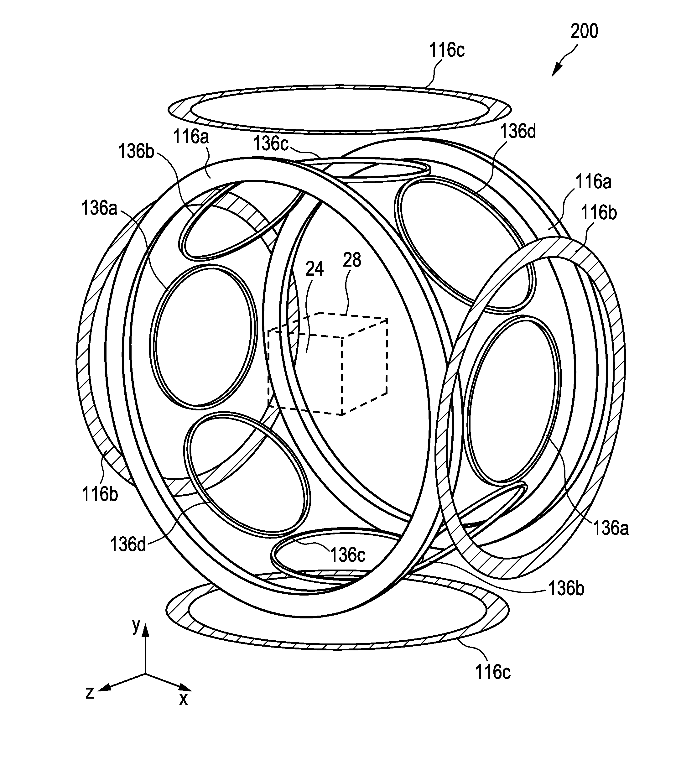
[0074]FIG. 4 shows a coil assembly 200 for generating and changing a magnetic field in a field of view 28. The coil assembly 200 is particularly able to generate and change / move a magnetic field 60 as shown in FIG. 5 in the field of view 28, said magnetic field 60 having a line-shaped first sub-zone 62 having a low magnetic field strength and a second sub-zone 64 having a higher magnetic field strength. For this purpose the embodiment of the coil assembly 200 shown in FIG. 4 comprises four pairs 136a, 136b, 136c, 136d of first coils, which are arranged along a ring around the field of view 28. The two coils of each pair are opposingly arranged on opposite sides of the field of view 28 at equal distance from the isocenter 24 and at equispaced angles along the ring. The centers of all first coils 136 and the isocenter 24 are thus in the same xy-plane. The magnet assembly 200 further comprises one pair 116 of second coils opposingly arranged on opposite sides of the field of view 28 at...
PUM
 Abstract
Description
Claims
Application Information